If I read it correctly, we are talking about Tibi's original circuit and it works from +- 36V. I claim that there is no audible difference between 48V and 50V in Tibi's original.
The rectifier PCB can be jumpered, no need to install 0.22 ohms there.
Tim
The rectifier PCB can be jumpered, no need to install 0.22 ohms there.
Tim
Resistors of a CRC rectifier PCB are additional resistors in the current source. This affects the Q17 circuit so that it first sounds softer in the bass and at higher levels muddy to distorted.
Through my current experiments I can determine that the very small internal resistance of the power supply limits the potential of the amplifier in the bass. This is an effect that cannot occur with Tibi's original PCB because the flat coil has too large losses.
Stef recently described this effect when he switched from the switching power supply to the toroidal transformer and achieved an increase in bass performance. This is due to the different internal resistance of the different current sources.
Tim

As Tim says, with a CRC we have bass and dynamic concerns. With the SMPS Connex, the result was not very good in the end compared to an analog power supply (on the Dynaudio Contour which requires a lot of current). The Connex works best with Class D or Class A amps.
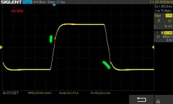
For a Q17 with one pair, between 48V and 53V is fine.
With a P2 below 58V, we have this jag on the signal. The lower the voltage, the stronger the deformation.
Stef.
For a Q17 with one pair, between 48V and 53V is fine.
With a P2 below 58V, we have this jag on the signal. The lower the voltage, the stronger the deformation.
Stef.
Attachments
The rectifier PCB can be jumpered, no need to install 0.22 ohms there.
Tim
I did a comparison between a shunted CRC PCB and a PCB with only a single backplane, I heard a difference. Apparently, the current is more important and optimized with a single backplane. This is reflected in the dynamics.
Stef.
Attachments
All Cees psu is meant for center tapped transformer configuration. An active rectifier can’t be used with this board.
I believe Tibi developed an active rectifier that can be used for center tapped configurations.
I believe Tibi developed an active rectifier that can be used for center tapped configurations.
Vunce is correct. If you are going to use synchronous/active rectification with the All Cee’s PSU, just be sure you use something designed for center tapped rectifiers, like from Evotronix - the Universal version.
Don’t use one that uses the LT4320 active bridge controller with the All Cee’s PSU. It is incompatible.
Best,
Anand.
Don’t use one that uses the LT4320 active bridge controller with the All Cee’s PSU. It is incompatible.
Best,
Anand.
Hello,
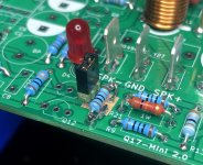
I finished the second Q17-Mini 2.0 board. It works. 😎
This consumes 21W @ 230V with two boards and the power supply à 49Vdc (Vishay bridge).
They currently work with R32 shunted without problem. The residual noise floor (DC offset) is 12mVPkPk and less than 1mvRMS without signal.
I still have several checks to do to verify that everything is ok with two boards.
Stef.
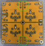
EDIT: I added the photo of the R32 jumper that I installed for testing.
I finished the second Q17-Mini 2.0 board. It works. 😎
This consumes 21W @ 230V with two boards and the power supply à 49Vdc (Vishay bridge).
They currently work with R32 shunted without problem. The residual noise floor (DC offset) is 12mVPkPk and less than 1mvRMS without signal.
I still have several checks to do to verify that everything is ok with two boards.
Stef.
EDIT: I added the photo of the R32 jumper that I installed for testing.
Attachments
Last edited:
Hello,
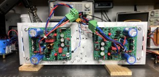
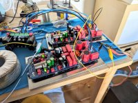
I didn't find any problem with 2 boards in stereo. The background noise is even better (7.5mVpkpk) once the configuration is complete with all the cables, HP protections and even a bridge/resistor/capacitor to filter the GNDPWD to earth.
The tests I did on speakers with my usual pieces are very good or rather I didn't have the syndrome, "It was better before". 😉
Have a nice week end,
Stef.
Attachments

My Q17s are alive and play beautiful music!
At least they did... I must have shorted the input while testing and R15 on one board went up in smoke... I hope that's the only thing that got damaged. Unfortunately I dont't have any spares of the 330 Ohms lying around, so I'll have to order some first. Well, the case is going to take some time anyway.
Any hints on what to check, to see if anything else broke? I wanna make sure before I order anything.
Cheers
Lars
Attachments
Hello,
I burned quite a few too. 😉
Check the power transistors , Q12 and change R15.
Afterwards, you start by turning on the board with 30Vdc. Consumption should be around 90mA per channel and almost 0 volts at output. If you have 21v at the output, you have Q12, Q7 or something else broken.
If you don't have 30V, turn the board on at 50V and if you have anything other than zero volts at the output cut off immediately and continue to check your components.
For the brave. If you try the board without heatsink, you have about 45 seconds before one of the power transistors burns (@50v). You can therefore test it for zero volts without having to reassemble everything on the heatsink.
Good luck.
Stef.
Thanks Stef. I will have a look tomorrow, if I can find anything obviously broken. (Tim also wrote me some suggestions.) If not, I'll just order some 330R.
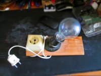
And not to be confused with modern halogen incandescent bulbs which pass less power but often display equivalence values like "100w" but written much smaller in a corner under the packaging "38w"It is becoming difficult to find bulbs of this type.
@Yurik_V
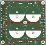
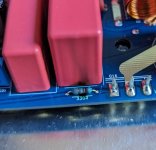
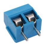
I had fun mounting one of the filter PCBs. I just bought the choke and the two chemical capacitors. The rest of the components is recovery on boards. It works correctly.
On the other hand, the PCB deserves to be improved. The holes for the connectors are too small. You can't even solder 0.75mm2 230V wire to it. I had to file the pins of the connectors so that they fit. The 4 holes of the choke are also not quite up to standard. There is also 2mm of space missing between the two-pin connector and the bridge on the right.
Stef.
Attachments

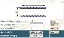
Alternatively, 1mm larger diameter needs only 15 turns and 30mm height.Hello,
A bit thick. You will have a beautiful tower 35mm high. 😉
http://www.circuits.dk/calculator_single_layer_aircore.htm
The tool gives an estimate. It would be necessary to check with a device.
You will also need to file the wire. The holes are 1.7mm in diameter.
Good night.
Stef.
Hole size shouldn't be an issue: I can extend them with a 2.0mm drill and solder the wire from both sides of the PCB. If the pads are large enough of course...
Attachments
Last edited:
- Home
- Amplifiers
- Solid State
- Q17 - an audiophile approach to perfect sound