
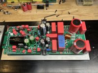
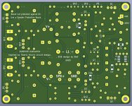
Tim's attention to detail and endless tweaking has further refined Q17. I've had this amp in my system for the last 10 days and it sounds wonderful. Not going to lie, the board layout seemed a bit busy at first. But after building it all components perfectly fit together like a puzzle. I took some liberty choosing resistor type and brand but followed the BOM recommendations exclusively for the rest of the components. This latest layout has even more tweaks then my freshly built boards. Having the UMS hole spacing is a helpful feature for buying ready machined Modushop chassis and the additional space given around L1 is welcomed.
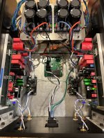
The Q17-V13 is built in the same chassis with psu as the previous Q17 using Stef's boards. It's been alternating between driving two different speakers, B&W CDM9NT (8R/90dB) and a DIY Tang Band W8-2314 coaxial in a TL enclosure (4R/85dB). The amp is dead silent when idling, delivers deep controlled bass, clear non-congested middle and fatigue free top end. My Keeper Amp's Stable is getting crowded, but will need to make room for this one 😉.
Big thanks to Tibi, Stef and Tim for sharing the Q17 Amplifier and the constant drive to improve upon the original!
Attachments

Hi,
Stef really wants to hold on to the dual power transistor concept, as do some others. So I'm looking for solutions how this can look like - but can't find one that behaves as universal at small signals, as well as at large signals, as the single pair does.
Here I noticed a detail that I overlooked in the previously published variant. That is the matching of R12 to the higher internal resistance of Q6. This is a very small adjustment, but while we're on the subject of perfecting it....
R12=52 ohms. That's it.
Regards Tim
Attachments

What happened to your design object in black and gold with blue components?Tim, just beautiful.
I will finish the FH9HVX and your boards I just have to build!!!
I did a lot of simulation runs of the Q17 with one, two and four pairs of power MosFETs and different parameter adjustments, with one result:
1 power pair: C10 = 56pF
2 power pairs: C10 = 100pF
4 power pairs: C10 = 220pF
The output filter should also be adjusted to L1 = 1.5 uH and C17 = 150 nF for several power pairs and C1 slightly increased to 680pF.
The point is that with several output pairs, the amplifier has levels that are too high in the MHz range, which is why some amplifier assemblies at the beginning of the project with several power pairs broke so quickly or didn't even play.
What can the double power stage do?
It cannot improve the control in the bass because the internal resistance of the amplifier remains the same due to the additional source resistors.
It is more suitable for higher loudspeaker impedances than for low ones, because the filters of the amplifier are not adjusted - see post before.
It can't deliver higher power, because in the large signal behavior the switching pulses produce more distortion than the single variant.
It cannot convince in the small signal behavior because of the imbalance of the power MosFET.
It is more expensive
It needs more holes on the cooler
It looks more important
In summary:
For more power and impedance matching to a 2 ohm load, the amplifier needs to be completely reworked. This also requires a higher supply voltage and a higher gain factor.
Good morning,
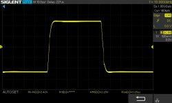
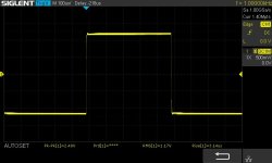
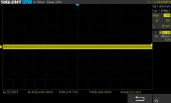
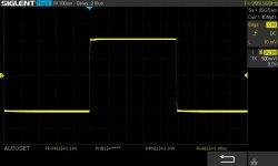
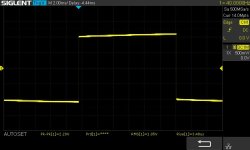
I tested the the Q17-Turbo with BD139-16 in Q12 stick on the heatsink. It causes an oscillation of 13MHz as with the BD139G. It is therefore confirmed that the BD139 whatever its version does not work if it is connected to the heatsink. This oscillation does not exist if the transistor is soldered on the component side.
I will now test the Toshiba TTC011B another candidate with better specs.
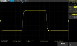
I also put you the measure with the KSC1845 in Q12. No problem that it is soldered on the component side or below stick to the heatsink.
To be continued in the next episode.
Stef.
I tested the the Q17-Turbo with BD139-16 in Q12 stick on the heatsink. It causes an oscillation of 13MHz as with the BD139G. It is therefore confirmed that the BD139 whatever its version does not work if it is connected to the heatsink. This oscillation does not exist if the transistor is soldered on the component side.
I will now test the Toshiba TTC011B another candidate with better specs.
I also put you the measure with the KSC1845 in Q12. No problem that it is soldered on the component side or below stick to the heatsink.
To be continued in the next episode.
Stef.
Attachments

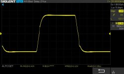
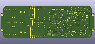
This is the second part of the measurements.
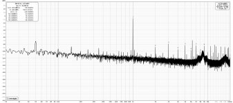
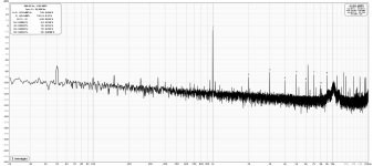
The good news is that there is no more oscillation with the Toshiba TTC011B, however the curves are not very good in my opinion. Worse than with the BD139 soldered on the component side or the KSC1845 whatever its position. The measurements of the Q17-Turbo also seem worse to me than the Mini (one pair Q17).
I also added the spectrum with the KSC1845 that I forgot to put earlier.
If you have any comments.
Stef.
Attachments

Last edited:
Personally, I do not validate the Q17-Turbo in its current state. I think it needs to be changed. That's not to say that it doesn't work or sound good, but it's a circuit that needs to be optimized.
Stef.
Stef.
First of all, I want to thank everyone for the great job you guys did, and releasing it to the public domain, and want to thank, most of all, Tibius (hope that I have spelled it correctly) for his fantastic work and dedication to this project.
Now, I just wanted to ask:
Would this audio amplifier be overkill, with a pair of 100w speakers (200W Stereo), rated at 4ohm (min) and 6ohm (nominal)? Would the amplifier destroy my speakers? They're not 8ohm's but they sure rock the place.
I searched the github page for specs, but could not find any info about the power output, I tried to read it on the comments, but its like one in the morning and I confess, I only have read, so far, till page 7.
I did some math, and if Tibius recommended a 300VA Transformer, I would say this amplifier would be between 225 and 240W? Am I close to it?
My only fear, I guess, is about the speakers being rated 6ohm nominal...
I'm planning to build this amp, with the "double output stage" option, my question would be:
I'm planning to send the files to the forge, are you guys planning to make any major tweaks any time soon? Just to know if it would be best to wait for it, or if I can start the process right away. Are the Gerber files (on github) updated, or is there an updated "double stage" posted here in the forum?
(Tomorrow morning I'll try to read the rest of the comments)
About the transformer:
Is "300VA transformer, with 2 separate secondaries at min.36Vac - max.42Vac", still the way to go? And how many Amperes? About 4 or 5 per rail?
.
So, that's it
Thank you guys so much for this project, can't wait to start soldering this beast
Last edited:
Hello,
yes we are having a battle for the best Q17.
There are old MosFet, the Fairchild FQA and FQP in the build. If you can get these, plus bs250 and 2n7000 in good quality, then you can build up the original from Tibi.
So this weekend I put a revised version online here, which can be built with currently available Mouser parts. See also the introduction one page earlier.
Vunce has presented above a construction on a smaller layout, but in the same way.
I forgot to answer your question:
My amplifiers have been tested on many hi-fi loudspeakers and have also worked on loudspeakers with difficult impedance characteristics without any problems.
Therefore, I can assure you that the Q17 leaves nothing to be desired in terms of power and control and if you set it up with a 300 W transformer for both channels, that is sufficient relative to an amplifier with over 2x500 W peak power (this has something to do with control and with the fact that today's amplifiers are no longer described with sine wave power).
Regards Tim
Last edited:
Hello,
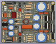
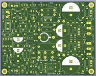
After almost a year, I finally updated the Q17-Mini PCB. This version does not bring big changes but improvements introduced over time.
Have fun.
Stef.
Changelog Q17-Mini 1.3.1:
https://github.com/stefaweb/Q17-a-QUAD405-audiophile-approach/tree/main/Q17-Mini 1.3.1
After almost a year, I finally updated the Q17-Mini PCB. This version does not bring big changes but improvements introduced over time.
Have fun.
Stef.
Changelog Q17-Mini 1.3.1:
- Moved C10 for better placement (thermal).
- Modified some parts of GND ground plane.
- The SMD capacitors footprints have been moved slightly away from the active components. Was difficult to solder by hand.
- Added JST-XH connector footprint for J1 (input).
- Changed U1 to OPA1611 (Sound warmer and a little less midrange).
- Updated C3/C6 to 47uF/25v (Nichicon Muse KZ UKZ1E470MPM1).
- Changed R29 and R30 to 100R (no more noise at power on)
- Replaced BD139G on Q12 with KSC1845 and updated footprint.
- Component references and equivalences added in schematic.
https://github.com/stefaweb/Q17-a-QUAD405-audiophile-approach/tree/main/Q17-Mini 1.3.1
Attachments
I guess I'll go with the mini version... Are they the same quality or better than the original project? I guess this would have a biased answer
I have not read tim and stef schematics, but I'll assume they are very similar
Does both versions uses mainly/only SMD components? I just would like to avoid them. I know technology is always evolving, and day by day, TH components are getting harder to come by... So I'll guess it will be a good time to start practicing soldering SMD components.
So the question is:
Shall I choose tim or stef version?
Stef's design definitely grabbed my attention, and it appears that does not uses many SMD components
Congratulations, your PCB looks amazing
Just have some questions about it.
For power supply, can I use Tibius design with a toroidal transformer?
And the design is for mono, right? For stereo I shall need a couple of them?
For speaker protection, any design available to use with this amp?
And for printing, I did some quotes using stef's design, and jlcpcb was the cheapest. Has anyone ordered from there before?
The version of me and Stef are very different. Stef's mini is tuned to TH components according to Tibi's original parts list and I have presented a version with SMD components here that is significantly modified compared to the original. See article:
https://www.diyaudio.com/community/...approach-to-perfect-sound.374507/post-7383991
and:
https://www.diyaudio.com/community/...approach-to-perfect-sound.374507/post-7384281
and
https://www.diyaudio.com/community/...approach-to-perfect-sound.374507/post-7384377
A decision aid:
Stef-Mini Advantages:
Not all components currently available for order via Mouser
Tim-Q17-V13SMD
https://www.diyaudio.com/community/...approach-to-perfect-sound.374507/post-7383991
and:
https://www.diyaudio.com/community/...approach-to-perfect-sound.374507/post-7384281
and
https://www.diyaudio.com/community/...approach-to-perfect-sound.374507/post-7384377
A decision aid:
Stef-Mini Advantages:
- very compact
- minimal and cheap components
- rational layout
Not all components currently available for order via Mouser
Tim-Q17-V13SMD
- 13th optimised version
- large PCB with SMD footprints
- designed for high power, too, due to extra wide traces
- Socket for a larger number of capacitors to be able to amplify all details of the music as low-loss as possible (this was mainly determined by comparison setups in many versions, as well as optimised on the simulation)
- Little extra: extra large socket for electrolytic capacitors up to 30 mm in diameter, also for very high capacities for ultra bass.
- All components for this layout can currently be ordered from Mouser.
Last edited:
On the Mini, all SMD components are optionals or "double footprint" of regular TH components.
I used jlcpcb many times without problem. Select the less expensive DHL shipping, le shipping time is the same than the more expensive. 😉
Stef.
EDIT: YOU NEED TO PRINT PCB IN 2 OZ.
I used jlcpcb many times without problem. Select the less expensive DHL shipping, le shipping time is the same than the more expensive. 😉
Stef.
EDIT: YOU NEED TO PRINT PCB IN 2 OZ.
Last edited:
- Home
- Amplifiers
- Solid State
- Q17 - an audiophile approach to perfect sound