Hello Steff,Quite the opposite of my straight-up version. 😎
By the way Tim if you pass by, what do you think of my problem with the BD139 "G"?
Stef.
I have formed an opinion to your question.
On the one hand there were statements from Tibi about a high amplification factor, on the other hand the transistor should be low-noise. For this objective I would not come now on the BD139.
Now to the next point:
I compare the Spice simulation with BD139 relative to the 2SC2240 (which Tibi uses as an alternative to the built-in 2SC1845 in the simulation). Now the simulation says that the BD139 consumes too much current and the working voltage to the power mosfet drops too much.
For this reason I would consider it a coincidence that it happened to you with the setup with the transistor to the cooler that the amplifier becomes more unstable. Factors are: the amplification factor of the BD139 - it must be very high - the GS voltages of the power mosfet, they must be very low with your tuning.
Therefore you can try the following: R24+R25 = 15k (17.5k + 100k in parallel), this will increase the current through the BD139 and R13 = 9.7 ohms (10 ohms + 330 ohms in parallel) to increase the working voltage of the power stage. With these two small adjustments, equivalence should be established according to the simulation model.
Regards Tim
Hello Tim,
Indeed, there seems to be a basic concern.
Still lots of tests to do when I come back from vacations. 😎
First of all, I would try to put a KSC1845 stuck to the dissipator instead of BD139, then I will try the BD139-16 when I received them and to finish the new resistances values with the BD139-16.
Stef.
EDIT: Are you sure a low noise transistor should be used there? When Tibi wrote to put a germanium transistor in this position we are far from the low noise. 😉
Last edited:
Hello Steff,
I think it was a quite bad idea with the germanium transistor. There are good transistors from Diodes Incorporated type ZTX, of which there are models with very ideal behavior, but they are not as easy to get as the KSC1845. I have also had good experiences and very ideal measurement write-ups of transistors from Toshiba and have also bought current products and used them for other projects. I had not noticed any potential where the KSC1845 behaves unfavorably in the use of the Q17. I also usually have a room-warm heat sink, so the need for thermal coupling just isn't there.
Tim
I am reviving the amp I used 20 yrs ago in the car. A 3 transistor mosfet amp using irf530 9530, the new one will use 610 9610 fets driving a 1943 / 5200 output pair. The 610 is biased against the 2sa1943. the 5200 acts as a current dumper.
There are good transistors from Diodes Incorporated type ZTX, of which there are models with very ideal behavior, but they are not as easy to get as the KSC1845.
HI Tim,
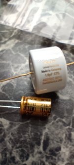
Give me the references of some transistors which could advantageously replace the KCS1845 in Q12. I would do some tests and measures. The ideal would be to find a replacement for the BD139 with the same package which is easier to handle than the TO-92.
In the meantime, it seems more secure to me to simply replace the BD139 with a KCS1845 on my PCBs. The pinout is written on the PCB to avoid any errors.
Stef.
hello Stef,
I checked my transistors. The 1845 I use has it printed: JCC1845F N41 the hFE is in the range of 379 to 410
I also found BD139, they have an hFE from 93 to 97
Then I found the following transistors in the format you requested: TTC011B,Q (Mouser: 757-TTC011BQ), they have hFE from 155 to 188.
The transistors from Diodes also have small cases, which does not correspond to your objective.
Regards Tim
The BD139Gs I've used have an hFE of 115 (sorted them out) but many are around 90. What about the "beta"?
For Mini or Turbo PCBs, I looked. I can easily put the two footprints TO-126 and TO-92 nested inside each other. It will be more versatile. If we can't find an "optimum" TO-126, I would remove the footprint to keep only the classic TO-92 by putting it near the edge of the PCB.
Stef.
For Mini or Turbo PCBs, I looked. I can easily put the two footprints TO-126 and TO-92 nested inside each other. It will be more versatile. If we can't find an "optimum" TO-126, I would remove the footprint to keep only the classic TO-92 by putting it near the edge of the PCB.
Stef.
According to the BD139 diagrams, the small-signal gain beta is slightly below the large-signal gain B. With the Toshiba TTC011, B and beta should be the same. The Toshiba is said to have a beta that is 1.7 times higher than that of the BD139, which can help with the problem.
Tim
Tim

Friends,
together with Q17 I am also working on PASS HPA-1 preamplifier, pcb by Jeff, I have a few extra pieces who would be interested contact me!
Regarding the internal cabling what would you recommend.
together with Q17 I am also working on PASS HPA-1 preamplifier, pcb by Jeff, I have a few extra pieces who would be interested contact me!
Regarding the internal cabling what would you recommend.
- Connection of the signal part - 2 twisted single core cables / high quality miniature shielded cable.
- Speaker output connection - 2 twisted single core cables / high quality speaker cable.
I'm no expert, so I am curious what others do. But personally I use..
- Connection of the signal part - generally Gotham GAC-1 or GAC-3, Mogami W2330 - cable choice all depends on chassis constraints
- Speaker output connection - 10awg (6mm2) or 12awg (4mm2) silicone wire twisted if the run is more than a couple inches
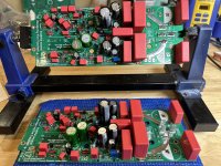
Looking good!
Do you have the heatsink holes drilled and tapped for the transistors and pcb mounting stand-offs? Correct mounting height and location of transistors should be known before they are soldered to the amp board. This eliminates stressing the legs if they are not aligned properly.
Do you have the heatsink holes drilled and tapped for the transistors and pcb mounting stand-offs? Correct mounting height and location of transistors should be known before they are soldered to the amp board. This eliminates stressing the legs if they are not aligned properly.
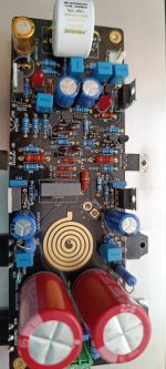
Guys, I got a problem,
I tried to power up this module via the 1A fuse and immediately left, the led in one side lit up and immediately went out. I checked each part 2 times to make sure it was in the right position. Where would you recommend to start looking? R29, R30 I used 10R 🙁
I tried to power up this module via the 1A fuse and immediately left, the led in one side lit up and immediately went out. I checked each part 2 times to make sure it was in the right position. Where would you recommend to start looking? R29, R30 I used 10R 🙁
Friends, all ok...
The charging current of the 3300uF capacitors was probably more than 1A. I replaced with bigger fuses and it works, ... 😀😀😀
The charging current of the 3300uF capacitors was probably more than 1A. I replaced with bigger fuses and it works, ... 😀😀😀


- Home
- Amplifiers
- Solid State
- Q17 - an audiophile approach to perfect sound