This be "amp porn" , too !
Ohhh , spiral inductor - how cool.
And it's got 2 red led's - sexy !
OS
Ohhh , spiral inductor - how cool.
And it's got 2 red led's - sexy !
OS
I don't know if the question has been posted already; I didn't see it in the thread: how can I lower the gain of the Q17 amp?
Modern devices, i.e. CD-players, streamers, pre-amps, often provide up to 2V output. 0.7V sensitivity corresponds to the 405 original, but does not really correspond to today's standard.
I'd like to connect a pre-amp to the Q17 that has an output of around 2V.
I understand the gain of U1 shouldn't be lowered to avoid instability, but how about e.g. Q7/Q8 or another place?
I apologize if the question is nonsense, but I'd prefer to avoid an attenuator in front of the amp.

I don't know if the question has been posted already; I didn't see it in the thread: how can I lower the gain of the Q17 amp?
For input sensibility at 1.5v: R17 = 7.32k
For input sensibility at 0.750v: R17 = 3.3k
Hi chat72,
Could you give me PCB version and if R32 is shunted?
The posted diagram is very old. R32 should be replaced with a strap (or shunted if wired).
The last diagram version is there Q17-Mini-schematic.pdf.
Regards,
Stef.
Could you give me PCB version and if R32 is shunted?
The posted diagram is very old. R32 should be replaced with a strap (or shunted if wired).
The last diagram version is there Q17-Mini-schematic.pdf.
Regards,
Stef.
Hi Chat,
approx. 40 mV DC offset is normal for R32 = 10 Ohm, this results from the current across R6.
Regards Tim
approx. 40 mV DC offset is normal for R32 = 10 Ohm, this results from the current across R6.
Regards Tim
I'm not sure PCB 1.1.4 can work without offset. Since then I have made quite a few modifications to the PCB. I think we can have no offset only starting from PCB 1.2.
As Tim said, try with R32=0R and also replace the BD139G with a KCS1845 or a 2SC2240GR (pay attention to the pinout).
Stef.
As Tim said, try with R32=0R and also replace the BD139G with a KCS1845 or a 2SC2240GR (pay attention to the pinout).
Stef.
Thank you all for reply, I think the offset is not that much problem for me. I will listen for them and I might upgrade to bigger version later.
Thank
Thank
Hello Stef,
I just dowloded your Q17 Turbo 1.0.1 files from Github, as well as Q17 mini 1.3.
In both directories, several files (namely the pdfs) are not readable, resp. report errors in PDF format.
I'm not sure if this comes from the download, or if some files are corrupt on Github.
Maybe you can check from your side.
Thanks
Christophe
Hi Christophe,
I tried. All seems ok with the files and pdf files. On-line on GitHub site or with zipped downloaded files.
Check that you have an older version of Acrobat Reader.
Download the zip again to check.
Stef.
I tried. All seems ok with the files and pdf files. On-line on GitHub site or with zipped downloaded files.
Check that you have an older version of Acrobat Reader.
Download the zip again to check.
Stef.
Cool.
I haven't had time to compare the KSC1845, BD139G, BD139-16 and TTC011B for Q12 yet since I got back from vacation. I'll try to get back to it this weekend.
Stef.
I haven't had time to compare the KSC1845, BD139G, BD139-16 and TTC011B for Q12 yet since I got back from vacation. I'll try to get back to it this weekend.
Stef.
Hello all,
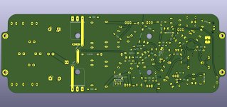
I have implemented some suggestions from the community in my Q17 design and now present this result.
One major aspect was SMD soldering directly to the board to avoid additional sockets. Also, this involved using suitable MosFET and transistors that are available and do not need to be matched. In this regard, Vunce successfully tested the Dual MosFET NDC7003P in my design. This is the smallest of the SMD devices, so footprint optimization was an important detail. On my layout, the SMD components are also turned in such a way that they are easy to solder by hand, even when soldering with a larger tip. This eliminates the following problem points: 1. the small MosFET and the small transistors, which are difficult or impossible to buy 2. the issue of thermal coupling of Q12 (which, according to the current experience of forum members, is more trouble than benefit).
Another aspect is the continuous perfection of the components, here I have the following contribution: Q6 = TK4K1A60F.
This is a Toshiba MosFET with perfect characteristics for the application. It has a low capacitance, is ideally suited for the task in terms of power and has a higher internal resistance. The last characteristic is a very ideal one to dominate the amplifier. In simulation, the Toshiba behaves more favorably, compared to the FQP and much more favorably than the IRF610. In the analysis and also in my test circuits, it turns out that the IRF9610 always works more as desired than the IRF610. The IRF9610 has mostly internal resistances in the range of 2 to 3 ohms, which is very favorable. This results in a pair for Q5 and Q6 of IRF9610 and TK4K1A60F.
The circuit also features the filters I designed (L2, L3, C27, R22, C-GND and R-GND) which provide outstanding silence. This silence results from the fact that due to the filters the input GND is not loaded with noise neither from the power side, nor from the driver stage via R6. This increases the dynamic range of the amplifier.
The circuit also contains the old wiring of Q13 and Q14 with a high series resistor (as presented by Tibi at the beginning of the project) to achieve a high voltage stabilization for the driver stage. This effect is supported by the numerous capacitors on my layout, so that the amplifier can play finest nuances even in this form.
A further facilitation for the construction is the extended layout with a lot of space for the coil, the connection contacts (for usual flat plugs with p = 5mm), as well as a hole pattern in the standard 80 x 40 mm grid size.
Finally, a very practical point:
There is a parts list, with components that Mouser has in stock.
I tested the Q17 in this version single-channel at 500W transformer with a 21 inch 4 ohm subwoofer, there he comes into sweat, with usual speakers, even with large ones, he plays in all volumes sovereign, detailed and controlled.
Have fun with building
Regards Tim
Attachments

Him Tim,
Great work.
1812CS-472XJLC is NRND. Do you have others suggestions?
Did you find time to update the diagram with the new filter?
Cheers,
Stef.
Great work.
1812CS-472XJLC is NRND. Do you have others suggestions?
Did you find time to update the diagram with the new filter?
Cheers,
Stef.
Hi Stef,
It's the same coil:
Manufacturer FASTRON
Manufacturer part number 1812AS-4R7K-01
The coil is available from other retailers, but I've learned here on the forums that the only true retailer that the DIY builder buys from is Mouser. Hence the list of Mouser products.
Which diagrams ?
Tim
It's the same coil:
Manufacturer FASTRON
Manufacturer part number 1812AS-4R7K-01
The coil is available from other retailers, but I've learned here on the forums that the only true retailer that the DIY builder buys from is Mouser. Hence the list of Mouser products.
Which diagrams ?
Tim
- Home
- Amplifiers
- Solid State
- Q17 - an audiophile approach to perfect sound