Isn’t this a Class B amplifier? I thought such machines were supposed to be comparatively efficient and cool-running.
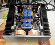
Into a 2U or 3U box, the Intelligent softstart + 2x PSU + 2x 500W toroidal transformer simply won't fit, ...Isn’t this a Class B amplifier? I thought such machines were supposed to be comparatively efficient and cool-running.
The transformers will be placed upright behind the front panel, ...
If your Toroidy order is not in production yet, alter it.
Order a single 500VA, 4 x 35v secondary trafo. Plenty of transformer for Q17.
…..just my thoughts 😉
Order a single 500VA, 4 x 35v secondary trafo. Plenty of transformer for Q17.
…..just my thoughts 😉

Isn’t this a Class B amplifier? I thought such machines were supposed to be comparatively efficient and cool-running.
HRDSTL have fun. 🙂
160VA per board for the single version (Q17-Mini) or 250VA per board for the P2/Turbo is in my opinion quite sufficient for normal use. 50VDC for the single, 60VDC for the P2/Turbo but work very well at 50VDC (x25) and is more secure If mains power supply has large variations.
Switching power supplies also work well, but I find that the low frequencies are too dry and fast.
By tightening well, you can put a lot of things in a "small box". 😉
Stef.
Attachments
Last edited:
Hello,
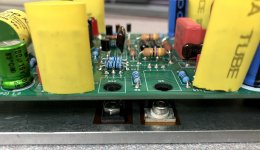
I just discovered a problem with the positioning of the BD139 (Q12) on the Q17-Turbo.
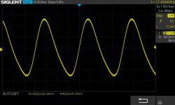
If I put the BD139 on top (photo 1) everything works fine. If I put the BD139 below (so that BD139 is on the heatsink for better thermal management), I have an oscillation (see picture). The problem is present with or without signal (the scope picture is without signal).
I tried on my two boards I built and I got the same result. On top ok, below not ok.
I had never noticed the problem because until now I had never installed the transistor underneath during my various tests for practical reasons.
So beware of those who build the Q17-Turbo with my PCB. Don't put Q12 under the PCB.
For the moment, I have not found the reason but if anyone has an idea, I am interested. It would also be nice if someone else could try to see if they have the same problem (you need a scope).
Stef.
I just discovered a problem with the positioning of the BD139 (Q12) on the Q17-Turbo.
If I put the BD139 on top (photo 1) everything works fine. If I put the BD139 below (so that BD139 is on the heatsink for better thermal management), I have an oscillation (see picture). The problem is present with or without signal (the scope picture is without signal).
I tried on my two boards I built and I got the same result. On top ok, below not ok.
I had never noticed the problem because until now I had never installed the transistor underneath during my various tests for practical reasons.
So beware of those who build the Q17-Turbo with my PCB. Don't put Q12 under the PCB.
For the moment, I have not found the reason but if anyone has an idea, I am interested. It would also be nice if someone else could try to see if they have the same problem (you need a scope).
Stef.
Attachments

Stef,
Is your BD139 metal backed or fully packaged? Do you notice different behavior (audible) when heatsink mounted?
Is your BD139 metal backed or fully packaged? Do you notice different behavior (audible) when heatsink mounted?
BD139G = metal
I do not tried on a speaker. The sinus and square curves are too bad with the oscillation to test on a speaker.
Stef
I do not tried on a speaker. The sinus and square curves are too bad with the oscillation to test on a speaker.
Stef
Is your heatsink connected to ground?
Strange…..
I used a fully packaged BD139 and have been playing the amp for the past couple weeks without any issues. It sounds quite good actually. Try replacing the BD139 with an insulated version and make sure your heatsink is grounded.
I have not measured with an O-scope though.
Strange…..
I used a fully packaged BD139 and have been playing the amp for the past couple weeks without any issues. It sounds quite good actually. Try replacing the BD139 with an insulated version and make sure your heatsink is grounded.
I have not measured with an O-scope though.
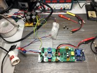
The BD139G is isolated from the heatsink with a plastic film. The aluminum plate on which the Q17 board is screwed is for the moment just placed on the workbench.
I will try lifting the BD139 slightly so that it is no longer in contact with the heatsink at all to see if that changes anything. I'm going to rummage through my boxes to see if I find an all plastic BD139.
But hey, the only big difference since the BD139 is isolated from the heatsink is the length of the legs.
Stef.
I just noticed it's the onsemi transistor. in general found BD139G quite bad (G stands for giant s**t). ST version is a much better bjt.BD139G = metal
I do not tried on a speaker. The sinus and square curves are too bad with the oscillation to test on a speaker.
Stef
Do ground the heatsink and try.
I removed the screw and unstuck the BD139 from the heatsink by 2mm with a screwdriver and I no longer have any oscillation!!
I will look at what I have in stock to replace the BD139G.
This story is very mysterious.
Stef.
I will look at what I have in stock to replace the BD139G.
This story is very mysterious.
Stef.
Is it possible the physical stress of being tightened down on the sink caused the problem? I’d be wary of that individual transistor.
To shut me up…
Please ground the heatsink and re-connect that BD139 the same way it was.
Curiosity has got the better of me🤪
Please ground the heatsink and re-connect that BD139 the same way it was.
Curiosity has got the better of me🤪
I tested the transistors before installing them. The transistors are installed in position on the heatsink before being soldered. No mechanical stress.
I found two plastic BD135-16. It's a bit caviar for pigs in this position but it should work. Will try.
I will also connect the ground/earth with the BD139 to see.
It also annoys me not to find the cause, especially since I used the BD139 instead of the original 2SC2240 to have a good, easy-to-install contact on the heatsink.
Stef.
Heck, the BD135 is -45v max. This is going to be too short. I'll have to find some plastic ones.
I can still find BD139, BD139-10 or BD139-16 from STMicro without worry.
I'm a little lost on the right model to take. The data sheet is not specific on this.
Stef.
I can still find BD139, BD139-10 or BD139-16 from STMicro without worry.
I'm a little lost on the right model to take. The data sheet is not specific on this.
Stef.
- Home
- Amplifiers
- Solid State
- Q17 - an audiophile approach to perfect sound