Some pictures.
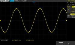
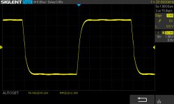
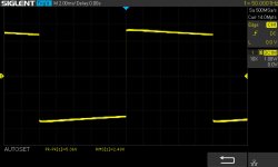
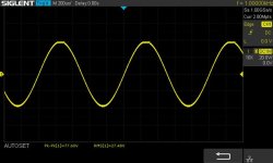
Sorry, do not find square 1kHz in my archive. I've 50Hz and 20KHz.
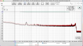
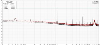
All these measures were done with the first prototype and a SMPS.
I've to find time to redo the measures with the final boxed version.
I still have some PCB if you want to try.
Regards,
Stef.
Sorry, do not find square 1kHz in my archive. I've 50Hz and 20KHz.
All these measures were done with the first prototype and a SMPS.
I've to find time to redo the measures with the final boxed version.
I still have some PCB if you want to try.
Regards,
Stef.
Attachments

Last edited:
Thank you! I will make a new board, put the bridge farther away at the end of the board.I still have some PCB if you want to try.
What do you mean by "mini version ran, but very unstable" ?I also put together two versions. One mini version and one with two pairs. The mini version ran, but very unstable, the 1kHz square is very bad, the 20kHz square looks like a saw. Two times the output transistors burned out for no reason. With two pairs it didn't even start. I will try to make a new board and move the coil away .
Many boards were made at the beginning of the thread, but no results are seen here. Also would like to see 1kHz and 20kHz quadrature. The amplifier is very unstable.
View attachment 1017648
View attachment 1017650
View attachment 1017651
View attachment 1017652
While testing with your 4ohm load, please show the signal on your power supply line as well. Please indicate volts/div and it would be good to see input signal.
I also suggest to move bridge coil in vertical plane. As it is now, it is far too close to cascode stage.
How is your power supply designed ? It is CRC ? Which output voltage ?
Please also change R29 and R30 to 100ohm.
Regards,
Tibi
The output transistors burned out spontaneously twice.What do you mean by "mini version ran, but very unstable" ?
I ordered a new board yesterday. A better layout. The coil has been stowed further away. When I get it, I'll try to get it running.I also suggest to move bridge coil in vertical plane. As it is now, it is far too close to cascode stage.
There are two power supplies. One is a 33v transformer, the other a 55v CRC.

Use an output fuse while testing the amplifier and take care on static charge handling.
I specifically asked if you use CRC filtering, because scope waves indicate clearly that you have a power supply problem.
CRC must NOT be used in a class B amplifier or A/B amplifier.
You can use CRC in a class A, class D, but not A/B or B.
Regards,
Tibi
I specifically asked if you use CRC filtering, because scope waves indicate clearly that you have a power supply problem.
CRC must NOT be used in a class B amplifier or A/B amplifier.
You can use CRC in a class A, class D, but not A/B or B.
Regards,
Tibi
So what's the correct rating? It varies a lot.Please also change R29 and R30 to 100ohm.
R29 and R30 are part of a capacitor multiplier made with Q13 &Q14 and must be set between 10ohm - for a fast turn on and 100ohm-for a slower turn on.
During power on sequence, capacitors C13 and C14 will charge trough R19 and R30 till the point where mosfets turn on and internal Rdson of each mosfet will bypass these resistors. This create a short transient region that must be kept short. Therefore C13 and C14 under 220uF and R29 and R30 under 100ohm.
If you have power on issues, reduce R29&R30 to 10ohm and C13&C14 to 47uF.
Regards,
Tibi
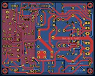
Lately, I spent some time, to design a PCB with dual ground plane on input section. This ensure signal guarding as well.
Hello Tibi,
When you were talking about a dual ground plane, were you talking about this kind of thing?
Regards,
Stef.
EDIT: for smk7
10K for R29 and R30 was an error.
I think too that R23 is now 8k2 (but not sure).
Attachments

Yes, that's good to follow and read this thread. 😉The schematic shows 10K!
I'll correct this in a future github update.
Regards,
Tibi
This is very true. I should do more testing before posting.This post was confusing.
Regards,
Tibi
Yes. Use small group of many vias, where is possible, to connect top to bottom.Hello Tibi,
When you were talking about a dual ground plane, were you talking about this kind of thing?
Regards,
Stef.
EDIT: for smk7
10K for R29 and R30 was an error.
I think too that R23 is now 8k2 (but not sure).
Regards,
Tibi
To fill the various holes? (Just to be sure).
I didn't dare to do it with the vias weighing that it could introduce pervert effects. I'm also doing a contest to use as few vias as possible. 😉 In the new version of the Mini that I am preparing for March, I have reduced the number of vias from 8 to 1.
Do we really need to add top ground plane on all the GND zone or only as in my example around the opamp?
Stef.
parasitic capacitance may appear. It is necessary to make transition holes in the polygons. This is my understanding.Do we really need to add top ground plane on all the GND zone or only as in my example around the opamp?
- Home
- Amplifiers
- Solid State
- Q17 - an audiophile approach to perfect sound