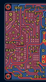
Vias is good used where is needed. There are several cases when this must avoided, but not here.To fill the various holes? (Just to be sure).
I didn't dare to do it with the vias weighing that it could introduce pervert effects. I'm also doing a contest to use as few vias as possible. 😉 In the new version of the Mini that I am preparing for March, I have reduced the number of vias from 8 to 1.
Do we really need to add top ground plane on all the GND zone or only as in my example around the opamp?
Stef.
Top and bottom ground planes are already connected by numerous parts that are gnd connected, but adding more vias will make gnd plane more "compact", reducing planes resistance and avoiding any possible ground loops.
You may add gnd vias near input signal connector and around opamp.
Regards,
Tibi
Thank you for the explanations. I think I understood the principle.
One last question: does the number of VIAs increase the price of the PCB at jlcpcb.com?
Stef.
One last question: does the number of VIAs increase the price of the PCB at jlcpcb.com?
Stef.
From my experience with jlcpcb, not so much
Price jump considerably when you go for enig, castelated holes, 2oz, metalised edges, etc..
Regards,
Tibi
Price jump considerably when you go for enig, castelated holes, 2oz, metalised edges, etc..
Regards,
Tibi
2os is costing a lot. I've see. But needed for a so small board.
PCBs with Gold have become overpriced! To say that I did it systematically golden 10 years ago. Newworld!
Like this. Is it okay or is it too much?
I will do a simulation of the gerber to see the cost of the VIAs with new files.
It's the last, I promise. 😉
Regards,
Stef.
PCBs with Gold have become overpriced! To say that I did it systematically golden 10 years ago. Newworld!
Like this. Is it okay or is it too much?
I will do a simulation of the gerber to see the cost of the VIAs with new files.
It's the last, I promise. 😉
Regards,
Stef.
Attachments
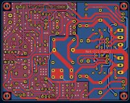
There are few places where is not needed for a gnd island, but overall is OK.
What I'll take care is to have gate and base stoppers as close as possible to transistor. Maybe you can correct this.
Regards,
Tibi
What I'll take care is to have gate and base stoppers as close as possible to transistor. Maybe you can correct this.
Regards,
Tibi
I tried for R7 and R8 but no space and the impact to move the 2 big caps was unmanageable. The curent version works. I have to be able to live with these resistances like that. Only 28mm distance. 😉
I'll remove the small islands.
Stef.
I'll remove the small islands.
Stef.
Attachments
Last edited:
Hello,
I've a question concerning the ZVN4206.
This transistor exist in 2 references: ZVN4206A and ZVN4206AV
https://www.diodes.com/assets/Datasheets/ZVN4206A.pdfhttps://www.diodes.com/assets/Datasheets/ZVN4206AV.pdf
I previously purchased the AV version and I need more units but the AV version is not available until August 2022.
I checked the data sheet and I don't see the difference.
An idea?
Regards,
Stef.
Last edited:
Thanks you.
Out of stock everywhere.
Found some on Ali but 20 units !! and not sure that the picture correspond to the shipped product.
https://www.aliexpress.com/item/1005003326169932.html
Or on eBay for 50 units from USA...
Stef.
Out of stock everywhere.
Found some on Ali but 20 units !! and not sure that the picture correspond to the shipped product.
https://www.aliexpress.com/item/1005003326169932.html
Or on eBay for 50 units from USA...
Stef.
Hello Stef,
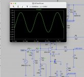
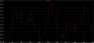
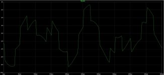
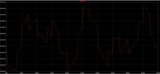
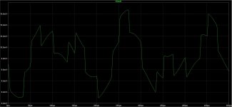
I have last done transient simulation with the following function generators, this at levels from 0.05mV to 0.5V at the input. This is to study small signals / large signals, harmonic behavior (square waveforms amplification) and aspects how capacitors for voltage stabilization affect the amplifier back.
1. sine 6kHz
2. sine 100 Hz
3. pulse 0,03ms negative amplitude 10kHz
4. pulse 0,02ms positive 0,05 ms delay 10kHz
All 4 signals at the same time of course.
Regards Tim
Attachments
Hello Stef,For Tim le king of LTSpice.
I got into it too. Quite complicated and with a horrible interface, but you get used to it. The software often crashes.
What do you think of the mods on the input?
Regards,
Stef.
two things:
1. the simulation with the GND resistor R32 is much closer to reality.
2. I threw out the input resistor again and by installing an inductance L2 with an internal resistance of 7 - 10 Ohm (6.8 uH to 15 uH) the gain of the amplifier drops sufficiently (by 3 to 4 dB).
I expect that the amplifier loses authenticity when the resistance between the capacitors C2 and the OPA is increased. This changes the balance of the feedback from the output (I know, this is a DC servo and not feedback in the usual sense, but then it would make absolutely no difference how big the resistance R23 is. But since a difference between 10k and 8k of R23 can be heard, C2 does not behave ideally, but as an erroneous capacitor with a higher error angle. Therefore, no single low ESR capacitor works well as C2).
Tim
Hello
a new audio JFET is available from Technics Instruments:
https://www.mouser.de/ProductDetail/Texas-Instruments/JFE150DCKT
maybe this one will be useful at one time in the future. I have not yet been able to get the Spice model to work in LTspice, this could be due to the 5 connections - JFET + protective diodes. It is also produced as a dual, but it is not yet listed at Mouser.
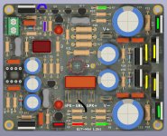
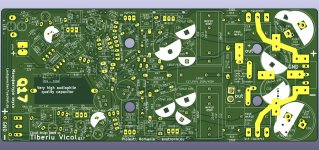
For the next Q17 test I have now ordered PCBs and these are based on the optimisation with the LTspice model on the one hand, so I have also made a modification to the ground system and I want to test Q12 as MosFET.
Q7 as JFET does not simulate nicely until now, especially in the small signal range, there should still be a lot of background noise. That's why I'm putting this on hold.
The PCB looks totally chaotic, as usual, but that doesn't matter to the electricity. In any case, many design notes have been incorporated, so I can see if they help.
Tim
a new audio JFET is available from Technics Instruments:
https://www.mouser.de/ProductDetail/Texas-Instruments/JFE150DCKT
maybe this one will be useful at one time in the future. I have not yet been able to get the Spice model to work in LTspice, this could be due to the 5 connections - JFET + protective diodes. It is also produced as a dual, but it is not yet listed at Mouser.
For the next Q17 test I have now ordered PCBs and these are based on the optimisation with the LTspice model on the one hand, so I have also made a modification to the ground system and I want to test Q12 as MosFET.
Q7 as JFET does not simulate nicely until now, especially in the small signal range, there should still be a lot of background noise. That's why I'm putting this on hold.
The PCB looks totally chaotic, as usual, but that doesn't matter to the electricity. In any case, many design notes have been incorporated, so I can see if they help.
Tim
Attachments

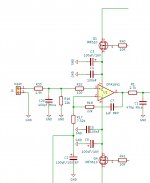
There is a LPF after opamp that limit amplifier BW at ~125KHz.
I do not use input LPF because internal cabling and PCB layout can eliminate any EMI. Cabling matter, pcb layout mater a lot.
If you want to "secure" input opamp I would go for a LPF at 1MHz. For this use 1K5 with 100pF.
Hello Tibi,
I have a question.
Why did you recommend such a high cutoff at 1MHz for the LPF?
Best regards,
Stef.
Attachments
The scope of input filter is to block any radio interference that may alter amplifier performance.
The most "dangerous" interference is coming from 2.4GHz-2.5GHz where bluetooth, wifi and microwave oven's are the main source of noise.
Another strong source of noise are mobile phones. These range from ~900Mhz and up.
1Mhz input LPF is quite OK. Next 125KHz LPF will kill create a second pole that may kill even LW radio.
However, for a good amplifier, a metal enclosure is a must.
Regards,
Tibi
Hello Tibi,
It's for my big fingers that hang out. 😉
Great. It's good to cut high. The CDE 100pF Mica is affordable (and I have a few CD15 in stock to try out). If we go to higher values (like 1nF) to cut lower, the price (or the size) explodes.
With the addition of the LPF+R22, do we need to readjust R17 (7k32) to stay with a 1.5v sensitivity?
Regards,
Stef.
- Home
- Amplifiers
- Solid State
- Q17 - an audiophile approach to perfect sound