hi Tibi,
Choosing such a high cut off frequency ( 1MHz) for the input low-pass filter may result in intermodulation products caused by the OpAmp. Unwanted inputnoise is also amplified by the opamp gainstage. I would recommend an LPF of approximately 200kHz. More than sufficient for audio signals ranging upto 20 kHz.
Choosing such a high cut off frequency ( 1MHz) for the input low-pass filter may result in intermodulation products caused by the OpAmp. Unwanted inputnoise is also amplified by the opamp gainstage. I would recommend an LPF of approximately 200kHz. More than sufficient for audio signals ranging upto 20 kHz.
Quick question guys on the opa1641 orientation on the original tibi layout. I see from the gerber view the opamp sides have 2 white lines with being bigger than the other. Then the datasheet of 1641 from the below pic has a notch on one of the sides. Please let me know which side of the white lines does the notch on the opamp goes?
Thanks


Thanks
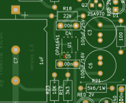
The schematic shows a 100nf decoupling cap at pin 7. The PCB image shows
that right where "C4" is printed, so I would say that is pin 7. Pin 6 goes to 22K resistor, so that is
further confirmation.
that right where "C4" is printed, so I would say that is pin 7. Pin 6 goes to 22K resistor, so that is
further confirmation.
Correct. That larger line indicates the pin 1 of the OPA.The schematic shows a 100nf decoupling cap at pin 7. The PCB image shows
that right where "C4" is printed, so I would say that is pin 7. Pin 6 goes to 22K resistor, so that is
further confirmation.
Attachments
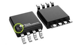
Yes, the notch indicates Pin 1 of the IC - that should go towards the larger line.
Pin 2 would be exactly where the silk screen legend has "C5" in the image below, and
Pin 7 would be where you see "C4" below.
Check for continuity between the input jack (not the grounded pin - the other one) and
the opamp pads on the PCB - the pad where you get a continuity beep is pin 3.
https://www.diyaudio.com/community/attachments/quad-405-q17-pcb-top-jpg.969776/
I just opened my opamp package from Newark/element14 and its a different marking which does not have the notch per the above data sheet but a single white line on one of the sides. Now this line should go towards the bigger white line on the PCB marking where OPA1641 silk screen marking?

Look carefully - one edge is bevelled - that edge would be on the side with pins 1 to 4.
See the cross section shown in this link
https://fdi.sk/posts/wrong-opamp/
http://wb5rvz.org/common/locatingPin1
See the cross section shown in this link
https://fdi.sk/posts/wrong-opamp/
http://wb5rvz.org/common/locatingPin1
Looks good! That purple solder mask looks awesome, and it is
so great to be able to see the traces on the PCB, unlike the
matte black which seems to be in vogue now.
so great to be able to see the traces on the PCB, unlike the
matte black which seems to be in vogue now.
Hello,
If anyone is interested, I made a small PCB of the 1.2uH coil using the Tibi KiCad footprint.
Gerbers and KiCad sources are available on my GitHub repository.
Regards,
Stef.
If anyone is interested, I made a small PCB of the 1.2uH coil using the Tibi KiCad footprint.
Gerbers and KiCad sources are available on my GitHub repository.
Regards,
Stef.
Attachments
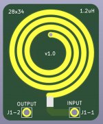
Thank you, yes first time printed in Purple and they seem to look very good. Progress so far with the parts in my stash, need to get the higher voltage electrolytics 220/2200uf in 63v.Looks good! That purple solder mask looks awesome, and it is
so great to be able to see the traces on the PCB, unlike the
matte black which seems to be in vogue now.
Hi,
just a little note: Nice board. Is it possible that you used 4.7 instead of 47ohm? In the picture it looks like a silver 4th ring.
One more thing, if it sounds very sleepy or dull, swap C7 for an audiophile foil. Regards Tim
just a little note: Nice board. Is it possible that you used 4.7 instead of 47ohm? In the picture it looks like a silver 4th ring.
One more thing, if it sounds very sleepy or dull, swap C7 for an audiophile foil. Regards Tim
Thanks will check the resistors as I remember checking every one in DMM before soldering. Also R26/28 I used my spare 22R but in 0.5w but the schematic says use 1W here. I hope the wattage would be fine otherwise need to replace with 1W.
Regarding C7 I like these Russian PIO caps but yes I do have other caps like Wima/Panasonic too. Will swap them later once I listen to these first.
Regarding C7 I like these Russian PIO caps but yes I do have other caps like Wima/Panasonic too. Will swap them later once I listen to these first.
Hi guys,
I have a quick question. What is the minimum voltage that can be used with a Q17 (one pair) for it to work?
It's for testing purpose ... without having to burn things...
I've found a variable DC symmetrical power supply to save fuses. 😉
Regards,
Stef.
I have a quick question. What is the minimum voltage that can be used with a Q17 (one pair) for it to work?
It's for testing purpose ... without having to burn things...
I've found a variable DC symmetrical power supply to save fuses. 😉
Regards,
Stef.
Amplifier was designed for at least +/-50V.
However, It would be interesting to know absolute minimum voltage operation.
For lower voltages, R24+R25 must be adjusted properly. For this, instead R24 use a 10K potentiometer.
At ~+/-18V regulators will stop to provide any regulation, but you may go as low as ... maybe +/-10V
Regards,
Tibi
However, It would be interesting to know absolute minimum voltage operation.
For lower voltages, R24+R25 must be adjusted properly. For this, instead R24 use a 10K potentiometer.
At ~+/-18V regulators will stop to provide any regulation, but you may go as low as ... maybe +/-10V
Regards,
Tibi
- Home
- Amplifiers
- Solid State
- Q17 - an audiophile approach to perfect sound