Hello Stef,
my Q17 amplifiers that play have voltages from +-35V to +- 38V
I have already tested +-53V, but it was not satisfactory. Now I have a transformer that should produce +-45V at the active rectifier (500VA 2x ~30V). I hope the transformer works well...
Regards Tim
my Q17 amplifiers that play have voltages from +-35V to +- 38V
I have already tested +-53V, but it was not satisfactory. Now I have a transformer that should produce +-45V at the active rectifier (500VA 2x ~30V). I hope the transformer works well...
Regards Tim
Hi Tibi,
are you planning to make a version with a quasi-complementary output stage? OnSemi has very powerful N-channel transistors. It was possible to use only one pair of transistors while achieving very high power. Without resorting to parallel connection of several pairs of transistors.
are you planning to make a version with a quasi-complementary output stage? OnSemi has very powerful N-channel transistors. It was possible to use only one pair of transistors while achieving very high power. Without resorting to parallel connection of several pairs of transistors.
Hi Tibi!
Thank you for all the force in handing this beauty, for free, to this community.
I wonder if the 'ideal bridge' you mentioned in this this thread, the ThT on #123, is suited for the Q17 as is?
Ed
Thank you for all the force in handing this beauty, for free, to this community.
I wonder if the 'ideal bridge' you mentioned in this this thread, the ThT on #123, is suited for the Q17 as is?
Ed
Hello,
True to my habits, I burned my Q17-Mini prototype again last night by testing the 10-30V power supply.
I reversed the GND and DC negative wire at 30v.
Resistors R13 and R32 instantly burned with beautiful red flames. I cut right away. The 1A fuses on the DC supply have not burned out.
I changed the two resistors but now I have 380mV of DC offset at output instead of 43mV.
I looked to see if other components were burned but nothing. The transistors seem ok. I put in another opamp. Same. If I send a 1KHz sine to the input, I recover it well at the output. I power the board at 30v. I took a reading of the voltages on the board.
If you have an idea where to look?
Steve.
Attachments

Thanks for the idea but C2 is ok and to be sure I replaced it.
I also checked C1.
I forgot to write on the diagram. I've 1.24v at opamp output (R1) instead of 1v.
Stef.
I also checked C1.
I forgot to write on the diagram. I've 1.24v at opamp output (R1) instead of 1v.
Stef.
Last edited:
Hello,
New findings:
1. changes to the GND system with R32 cause the amplifier to hum, here the DC offset is the smallest evil.
2. the MOSfet as Q12 leads to a kind of short circuit at the start of the amplifier, so I could not find an operating point that the amplifier works with it. After changing to the normal transistor the amplifier worked.
3. with the power supply via +-40V I have no luck either, the amp played only a few seconds, then got loud by itself and the fuse shut it down.
Regards Tim
Given your description, R10, R11 and R12 would have to be prime candidates for the unwanted offset. Did you measure their values?
Thanks a lot too.
They are ok. In fact, I checked all resistors and they are fine.
Just to be sure. Can we have a transistor which passes the tester which once energized in the circuit does not work as it should?
Currently, I tested all transistors except Q12, Q5, Q6, Q15 and Q17. I haven't tested them yet because whenever I've had problems with those, it's more like -45 or 45v at output.
Stef.
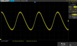
Me again. Maybe a lead.
I connected the board to a 50v power supply instead of 30v. Nothing is hot and consumption is normal.
I plugged the scope into it via an 8R load on the output. Input is shunted with a 100R resistor to ovoid noise.
I get a kind of sine at output!!
See screenshot.
Regards,
Stef.
I connected the board to a 50v power supply instead of 30v. Nothing is hot and consumption is normal.
I plugged the scope into it via an 8R load on the output. Input is shunted with a 100R resistor to ovoid noise.
I get a kind of sine at output!!
See screenshot.
Regards,
Stef.
Attachments
Last edited:
Hello Tibi, hello everyone,
I assembled my Q17mini boards using the PCBs designed by Stef1777
They have been working for a week, the results are promising.
Next step put in a case and enjoy 🙂
@Stef, I hope you will solve the problem on your prototype...


The boards operate at +/- 50V, linear PSU / 300VA
Best regards,
Julien
I assembled my Q17mini boards using the PCBs designed by Stef1777
They have been working for a week, the results are promising.
Next step put in a case and enjoy 🙂
@Stef, I hope you will solve the problem on your prototype...
The boards operate at +/- 50V, linear PSU / 300VA
Best regards,
Julien
Last edited:
@chickadee
At this time I have no plan to do a quasi-complementary output stage.
Fairchild transistors are powerful enough to drive almost any speaker.
Q17 design is open-source, you may fork the project and design any alternative you may consider appropriate.
@ed linssen
Thank you ! The ideal bridge mentioned here https://www.diyaudio.com/community/threads/ideal-bridge-rectifier-gb.333844/page-21#post-6212303 will work. To use active power supply, which come with this project, you need a smd bridge similar with Saligny Standard.
@stef1777
Great things are coming from smoke and sweat ! 🙂
@Tim1999de
I told you … 🙂
@juju35135
Congratulations !
Maybe you can comment on sound. How do you compare it with other amplifiers ?
Regards,
Tibi
Hello,
Well, I checked one by one the active components, the capacitors and the resistors. Everything seems ok. I don't understand where the problem comes from.
I even scanned the PCB to see if I saw anything burnt/cut. Nothing visible.
The Q17-Mini board is v1.1 that works and has been built by others as well.
Is there a method to find where this oscillation that I see on the scope comes from (only at 50v not at 30v). The DC offset being the same at 30v or 50v (around 350mV). With 1.2v at the amplifier output (R1) instead of the usual 1v.
Regards,
Stef.
Hello,
I solved the problem on the Q17 board. I had by mistake put a resistance of 100R on R32 instead of 10R.
Regards,
Stef.
I solved the problem on the Q17 board. I had by mistake put a resistance of 100R on R32 instead of 10R.
Regards,
Stef.
Hello,
@Stef
Good news, you found the problem, ready for further testing and optimization 🙂
@Tibi
Thank you for your support,
Not having the power supply for the speakers protection module yet,
I just listened to the Q17mini on cheap loudspeakers...
Anyway, the sound is powerfull, very clear with good bass.
This weekend I started the casing, drilled the heatsinks and started attaching the boards....
When everything will be OK and after a little burn-in I will do some comparative listening and will keep you informed.
Regards,
Julien
I still get flood of Q17 technical questions on private messages and my company email address.
I appreciate very much the interest this amplifier has generated and I do my best to answer to all of your messages, but a large number of questions are very technical that require elaborate answers and I want to remind that best place to have this discussion is this thread. This save me time and allow others to get information and do not repeat same question again.
Therefore, I kindly ask to use forum for technical discussions and private messages for private things.
Thank you !
Regards,
Tibi
Hello @tvicol /Tibi
A quick question regarding using a CRC psu board with your original Q17 amp pcb. I do have a set of these Prasi designed CRC psu boards with me with 60kuf capacitance per the post#450. https://www.diyaudio.com/community/threads/lt4320-based-active-rectifier.336572/post-5961968 I hope this psu is fine to power your Q17 and what rated transformer do you recommend having single pair of power transistors?
Thanks
Hello,
Q17 is a class B amplifier and I already mentioned that CRC should never be used in a class A/B or B amplifier. If you make use of any other boards that are not designed by me, make sure is not CRC, or make R =0ohm.
I surely can not and will not comment on others designs.
A 300VA trafo with +/-35Vac.
Regards,
Tibi
Sure thanks Tibi, point noted as I saw your earlier post of not using a regular CRC psu for Q17 being a Class B amplifier. But just thought of checking with you as the Psu that I have is based on the LT4320 and I am using 0.33 pair of parallel resistors. Then let me figure out for another psu as I forgot to print your Psu boards last time unfortunately 🙁 Maybe do a point to point wiring and make do with a breadboard or something similar on the lines of your psu recommended in your build guide.
- Home
- Amplifiers
- Solid State
- Q17 - an audiophile approach to perfect sound