Hello,
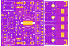
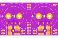
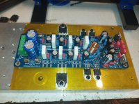
This is the version for replacing an original PCB or for building a Q17 amplifier, but in the original QUAD-405 style.
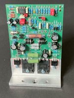
All 6 active components, prefinals, capacity multipliers and transistors for stabilization, are in close mechanical / thermal contact, through the metallized passages, with the aluminum profile.
The back of the profile will be insulated from the PCB with special thermal foil.
I have a few more PCBs to design and in the next series I will manufacture this PCB as well.
The PCB has the size of 82 x 118 mm and uses the same coil in 4 layers of 70 microns copper layer.
This is the version for replacing an original PCB or for building a Q17 amplifier, but in the original QUAD-405 style.
All 6 active components, prefinals, capacity multipliers and transistors for stabilization, are in close mechanical / thermal contact, through the metallized passages, with the aluminum profile.
The back of the profile will be insulated from the PCB with special thermal foil.
I have a few more PCBs to design and in the next series I will manufacture this PCB as well.
The PCB has the size of 82 x 118 mm and uses the same coil in 4 layers of 70 microns copper layer.
Attachments

Last edited:
If anyone has information on the positioning of the mounting and guide holes of the original aluminum T profile and wants to communicate them, I will be very grateful! Thanks!
Hi Atiq,
DIP8 is something for a daughterboard on this board. It is only possible to get this performance on such a tiny board because of the dense assembly on both sides. This has nothing to do with the large boards I have drawn.
Have you already received the boards with the two dip sockets?
DIP8 is something for a daughterboard on this board. It is only possible to get this performance on such a tiny board because of the dense assembly on both sides. This has nothing to do with the large boards I have drawn.
Have you already received the boards with the two dip sockets?
atiq19,
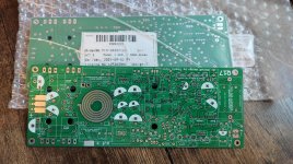
Where did you have those boards done ? Look at the inductor, does not look good.
No it's not what you are thinking, slight uneven finishing in the printed coil. It's a 'feature' of a horribly cheap product! The boards look absolutely fine in a close examination. JLC did a decent job, not using them for the first time. Proof will be in the pudding.
Basically it would be a totally useless option ... OPA1641 (1642) is probably the most low cost audiophile AO on the market, far above the AO quality that were used by QUAD. Who can't plant an SO-08 capsule, can't plant any 1206 resistor, as such you will have to request a module already planted ... In the PCB design you have to look in the design phase for a certain type of components existing on the market , in multiple sources. Alternative or special components being an expensive option that spoils the basic design ...there should be an option for dual op-amp in Dip8 on the pcb
Hi Jan,
What is wrong with the coil?
You don't want to describe the tin surface as a "quality defect", do you?
What is wrong with the coil?
You don't want to describe the tin surface as a "quality defect", do you?
Last edited:
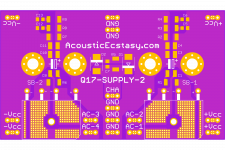
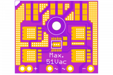
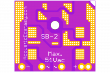
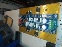
For the most demanding audiophiles, we designed a classic source, both to build an amplifier and to replace the original source in QUAD-405. Capacitors with screws of 51-52mm diameter and a capacity from 22,000 uF to 51,000 uF and a voltage of 63Vdc can be mounted.
Both classic rectifiers and synchronized rectifiers can also be mounted. The source also includes a "Lift Ground" module.
These PCBs will be launched in a few days.
Both classic rectifiers and synchronized rectifiers can also be mounted. The source also includes a "Lift Ground" module.
These PCBs will be launched in a few days.
Attachments
Last edited:
Tim, no problem, I'll rather use a separate inductor.🙂Hi Jan,
What is wrong with the coil?
You don't want to describe the tin surface as a "quality defect", do you?
I love castellated holes. 
I may suggest you to use castellated holes for those who may want to use lateral mosfets in place of Q5&Q6 and Q15&Q16. While normal holes to be used for verticals. With laterals, the sound is calm and very sweeeeet. Some people like this.
Regards,
Tibi
I may suggest you to use castellated holes for those who may want to use lateral mosfets in place of Q5&Q6 and Q15&Q16. While normal holes to be used for verticals. With laterals, the sound is calm and very sweeeeet. Some people like this.
Regards,
Tibi
- Home
- Amplifiers
- Solid State
- Q17 - an audiophile approach to perfect sound