Hi Tibi
Curious why you chose the 405 as the base in lieu of one of the later, opamp-free Quads.
Nostalgia? Or technical reasons?
Curious why you chose the 405 as the base in lieu of one of the later, opamp-free Quads.
Nostalgia? Or technical reasons?
Hi,
I wanted to keep original topology while improving all stages, so it may be called nostalgia too.
With my modifications a modern 606/707/909 can be constructed as well.
Regards,
Tibi
I wanted to keep original topology while improving all stages, so it may be called nostalgia too.
With my modifications a modern 606/707/909 can be constructed as well.
Regards,
Tibi
Last edited by a moderator:
Tibi,
I'm just a builder and diy guy, but I have wondered. The original Quad 405 had a quasi output. Yours is complimentary, so it should sound very different to the original circuit ? Just curious as Quasi amps sometimes have a warmer type of sound.🙂
I'm just a builder and diy guy, but I have wondered. The original Quad 405 had a quasi output. Yours is complimentary, so it should sound very different to the original circuit ? Just curious as Quasi amps sometimes have a warmer type of sound.🙂
Hi Jan,
In QUAD405 I do not see a quasi output. It is a combination of npn + pnp&npn.
Regads,
Tibi
In QUAD405 I do not see a quasi output. It is a combination of npn + pnp&npn.
Regads,
Tibi
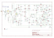
No, is not. QUAD405 make use of a complementary output stage npn + pnp, where the pnp is made using Sziklai Pair pnp + npn, also known as a CFP.
Regards,
Tibi
Regards,
Tibi
Hello!
Sorry for the inactivity, but summer always comes with a vacation ...
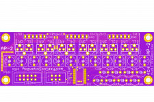
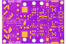
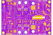
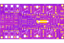
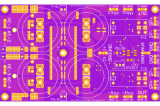
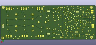
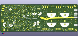
But I didn't rest for too long, but rather I made time for the new design ... The inspiration was maximum and the ones presented below resulted.
I launched all the PCBs at the factory, I will come back in the next days with details. Probably next week I will take possession of the PCBs.
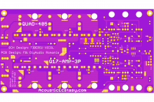
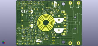
Because I had time, I also designed a version with 3 pairs of transistors.
I also modified the version with a pair of transistors.
The goal was to place the transistors under the PCB so that the width of the PCB would allow mounting on a 75mm heatsink. Respectively 100 mm heatsink width for the 3-pair version.
And for everything to be complete, we also designed two versions of preamplifier/selector, Solid State Relay and Synchronous Bridge.
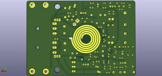
And because Tiberius insisted on a 4-layer coil, I designed such a coil.
It is a bit atypical and special from a constructive point of view, it is quite expensive because I chose PCB with a 2oZ copper layer (75 microns), but it has very small dimensions, 24x24x4mm.
The coil will come ready assembled by me and will be composed of two layers of 1.6mm PCB + an insulating layer of 0.6mm.
It cannot normally be ordered in 4 layers at the factory because the inner layers never exceed 0.5 oZ (18 microns). A special application for a 2 oZ internal PCB would cost extremely much.
Sorry for the inactivity, but summer always comes with a vacation ...
But I didn't rest for too long, but rather I made time for the new design ... The inspiration was maximum and the ones presented below resulted.
I launched all the PCBs at the factory, I will come back in the next days with details. Probably next week I will take possession of the PCBs.
Because I had time, I also designed a version with 3 pairs of transistors.
I also modified the version with a pair of transistors.
The goal was to place the transistors under the PCB so that the width of the PCB would allow mounting on a 75mm heatsink. Respectively 100 mm heatsink width for the 3-pair version.
And for everything to be complete, we also designed two versions of preamplifier/selector, Solid State Relay and Synchronous Bridge.
And because Tiberius insisted on a 4-layer coil, I designed such a coil.
It is a bit atypical and special from a constructive point of view, it is quite expensive because I chose PCB with a 2oZ copper layer (75 microns), but it has very small dimensions, 24x24x4mm.
The coil will come ready assembled by me and will be composed of two layers of 1.6mm PCB + an insulating layer of 0.6mm.
It cannot normally be ordered in 4 layers at the factory because the inner layers never exceed 0.5 oZ (18 microns). A special application for a 2 oZ internal PCB would cost extremely much.
Attachments
-
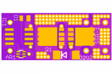 SSR-1-TOP.png77.6 KB · Views: 222
 -
 SB-1-TOP.png96.7 KB · Views: 218
 -
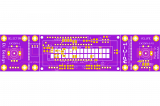 AP-CTRL-1-TOP.png89.2 KB · Views: 236
 -
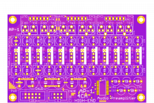 AP-2-TOP.png171.1 KB · Views: 256
 -
 AP-1-TOP.png124.4 KB · Views: 260
 -
 Q17-AMP-1P-BOT.png182.1 KB · Views: 468
 -
 Q17-AMP-1P-TOP.png224.6 KB · Views: 474
 -
 Q17-AMP-3P-BOT.png150.9 KB · Views: 473
 -
 Q17-AMP-3P-TOP.png196.3 KB · Views: 477
 -
 Q17-SUPPLY-TOP.png219.7 KB · Views: 226
Last edited:
A plethora of boards ! 😀
Sorin, It would be good if you may present schematics on the adjacent projects.
Regards,
Tibi
Sorin, It would be good if you may present schematics on the adjacent projects.
Regards,
Tibi
From the messages I have received so far, there is a great interest in a board that may be drop in replacement for the original QUAD405.
Regards,
Tibi
Regards,
Tibi
Hi Tibi,
Thanks for appreciation!
Yes, I will draw and present all the diagrams, nothing is secret, but this takes time. I have a different style ("Picasso style" 🙂 ) of PCB design, I never start from the diagram but from ideas and vision. This allows me to place or change components, materials, technology or design at any time or depending on the evolution of the design. As such, the initial schemes cannot be presented but must be prepared in advance.
Yes, I will carefully study the original PCB format of the QUAD405, I will do a little research on mechanical materials and solutions and then I will make a Q17 version that will easily and easily replace the original pcb.
Sorin, you have a sensational talent in PCB design, but sometimes Quad 405 / Q17 involves a PCB compatible with the old PCB used in Quad405.
Are you able to make a mechanical PCB 100% compatible with the original (Tibi Vicol Q17 version, with two pairs)?
If YES, you are the best PCB designer and any of your requests is in the field of PCB .
Are you able to make a mechanical PCB 100% compatible with the original (Tibi Vicol Q17 version, with two pairs)?
If YES, you are the best PCB designer and any of your requests is in the field of PCB .
Hello,
It's really great that so many boards are being created for the Q17, as it gives a lot of ideas on how to make it the best it can be.
I am very happy with the small amplifier that I have finished and it is now on the road for about 2 months for testing with hi-fi friends in Germany. Of course, they all expect it to play "better" than the finished products for thousands of Euros, I am curious to hear what I get to hear.
Another friend with a home cinema that is far too big - a whole roof only for watching films - of course needs maximum power, so it may be as much as 1000W per channel of music power. For the Quad 405, transformers for inverting the input signal are said to have been available as accessories, so that two Quad could be used bridged for speakers with higher impedance. My assessment of the Q17 is that with one pair of output transistors it is ideal for 4 - 8 Ohm speakers. With 3 pairs of output transistors, it should be ideal for 2 ohm loads, making it ideal for bridging and using as a power amplifier for PA speakers. To do this I have designed a layout that has both a pre-out for the amplifier module running inverted, and a switchover so that the amplifier can be switched from non-inverted mode to inverted mode. I expect that a 500VA transformer with 2x 35V is ideal for this amplifier. This will produce 50V - 53V DC.
A short description of the input:
The circuit is taken from the data sheet of the OPA1656 and misappropriated. I have already built a very detailed headphone amplifier with balanced output with it.
Since the circuit can be built identically for the application here, only + and - have to be exchanged at the input, it is very easy to use only one PCB layout to build an amplifier that can be switched between normal operation and bridge operation with a 3x change-over switch. This leads to the fact that I can use the very good working power supply for the operational amplifier from Tibi, which is on the board, to control the amplifier input as well.
To avoid being dependent on the impedance of the connected source, there is a pre-out for the amplifier, which is always operated non-inverted. The second amplifier is then supplied with audio signal via the pre-out when it is switched to bridge operation - playing inverted.
The OPA1656 is a very ideal and very new operational amplifier from TI, which I have already installed in many audio devices. So far, I am fully convinced of this amplifier, which plays great even in very many, even in not ideal installation conditions.
In order to save space, but also to use components that are readily available, I have slightly reduced the amplifier quality (compared to my optimised design). C27 and R22 are not absolutely necessary in this configuration, but in my opinion they contribute to stable operation without interfering.
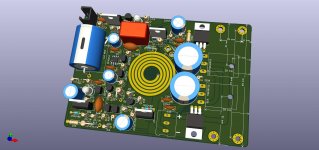
My goal with the layout is clearly a design for the use of high power peaks, especially in bridge mode. Sensitivity to the finest nuances is not the objective. For this reason, the large foils I used in the other layouts are missing. Instead, there are now sockets for large electrolytic capacitors with a snap-in socket and diameter of 25 - 26mm. These are to provide the current for pulses. So that the resistors don't get hot so quickly, I have made room for up to 7W models. Both the cheap square ones 9 x 9 x 25 mm and the nice ones from Vishay fit.
The layout fits in enclosures with a cooler width of 11 cm or more. I ordered a 15 cm high case for this amplifier, which is just big enough to fit both modules, a 500VA transformer and then also the board with the active rectifiers. The layout is pretty good for 15cm wide radiators, which I think it can use well at high power. The output transistors are not too close together and the board length is still acceptable at 22 cm.
Regards Tim
It's really great that so many boards are being created for the Q17, as it gives a lot of ideas on how to make it the best it can be.
I am very happy with the small amplifier that I have finished and it is now on the road for about 2 months for testing with hi-fi friends in Germany. Of course, they all expect it to play "better" than the finished products for thousands of Euros, I am curious to hear what I get to hear.
Another friend with a home cinema that is far too big - a whole roof only for watching films - of course needs maximum power, so it may be as much as 1000W per channel of music power. For the Quad 405, transformers for inverting the input signal are said to have been available as accessories, so that two Quad could be used bridged for speakers with higher impedance. My assessment of the Q17 is that with one pair of output transistors it is ideal for 4 - 8 Ohm speakers. With 3 pairs of output transistors, it should be ideal for 2 ohm loads, making it ideal for bridging and using as a power amplifier for PA speakers. To do this I have designed a layout that has both a pre-out for the amplifier module running inverted, and a switchover so that the amplifier can be switched from non-inverted mode to inverted mode. I expect that a 500VA transformer with 2x 35V is ideal for this amplifier. This will produce 50V - 53V DC.
A short description of the input:
The circuit is taken from the data sheet of the OPA1656 and misappropriated. I have already built a very detailed headphone amplifier with balanced output with it.
Since the circuit can be built identically for the application here, only + and - have to be exchanged at the input, it is very easy to use only one PCB layout to build an amplifier that can be switched between normal operation and bridge operation with a 3x change-over switch. This leads to the fact that I can use the very good working power supply for the operational amplifier from Tibi, which is on the board, to control the amplifier input as well.
To avoid being dependent on the impedance of the connected source, there is a pre-out for the amplifier, which is always operated non-inverted. The second amplifier is then supplied with audio signal via the pre-out when it is switched to bridge operation - playing inverted.
The OPA1656 is a very ideal and very new operational amplifier from TI, which I have already installed in many audio devices. So far, I am fully convinced of this amplifier, which plays great even in very many, even in not ideal installation conditions.
In order to save space, but also to use components that are readily available, I have slightly reduced the amplifier quality (compared to my optimised design). C27 and R22 are not absolutely necessary in this configuration, but in my opinion they contribute to stable operation without interfering.
My goal with the layout is clearly a design for the use of high power peaks, especially in bridge mode. Sensitivity to the finest nuances is not the objective. For this reason, the large foils I used in the other layouts are missing. Instead, there are now sockets for large electrolytic capacitors with a snap-in socket and diameter of 25 - 26mm. These are to provide the current for pulses. So that the resistors don't get hot so quickly, I have made room for up to 7W models. Both the cheap square ones 9 x 9 x 25 mm and the nice ones from Vishay fit.
The layout fits in enclosures with a cooler width of 11 cm or more. I ordered a 15 cm high case for this amplifier, which is just big enough to fit both modules, a 500VA transformer and then also the board with the active rectifiers. The layout is pretty good for 15cm wide radiators, which I think it can use well at high power. The output transistors are not too close together and the board length is still acceptable at 22 cm.
Regards Tim
Attachments
Sorin, you have a sensational talent in PCB design, but sometimes Quad 405 / Q17 involves a PCB compatible with the old PCB used in Quad405.
Are you able to make a mechanical PCB 100% compatible with the original (Tibi Vicol Q17 version, with two pairs)?
If YES, you are the best PCB designer and any of your requests is in the field of PCB .
Thanks Victor!
In Romanian it would be something like: Pai nu fac eu? (Well, don't I?) 🙂)
I just started the design documentation, pictures with the original module and other information ... I notice that the power supply is exactly +/- 50Vdc and as such in 4R it is mandatory two pairs of ends.
Also on the width of 90 mm (90/92 / 95mm) enters, in line, 4xTO3P + 2xTO220.
I have a problem with this aluminum T profile. Many clones use a 3mm thick profile, the original profile seems to be 3.5mm thick, but I would like a T profile of at least 5-6 mm thick ... I'm still looking ...
Last edited:
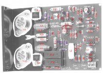
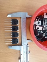
It seems that I was wrong ... Many Q-405 clones on the market are 90-95 mm wide, but many buyers complain that they could not mount them instead of the original modules which in all probability are 83 mm width. As such, we cannot place anything on the aluminum radiator except the final transistors, as in the attached photo. The transistors for multiplying the capacity will be placed on the back of the board (SMD, D2PAK) and will be cooled by metallized passages also by the aluminum radiator.
I will choose IRF630 / 9630 because they are available in D2PAK capsule. Any other option is quite complicated to implement.
I will choose IRF630 / 9630 because they are available in D2PAK capsule. Any other option is quite complicated to implement.
Attachments
Hello Tibi,
I have re-sorted your KiCAD file and deleted the large footprints for the Quad 405 Case. The resistors must also stand on this PCB, but I wanted to know if it was possible in principle to get the amplifier with your components on a PCB that could be attached to the aluminium angle of the Quad 405 and that is only 83 x 120 mm in size. Another aspect was the keeping of the printed coil, which made the task much more difficult. Otherwise it would have been too easy.
Now we will see what sorinsistem makes to solve this.
Regards Tim
Attachments
Last edited:
Thanks Tim, this look very nice !
At this point I think we should ask if anybody have exact dimensions of the original QUAD405 pcb and heatsink.
Regards,
Tibi
At this point I think we should ask if anybody have exact dimensions of the original QUAD405 pcb and heatsink.
Regards,
Tibi
Yes, it would be very good if someone measures an original.
Basically, the mounting holes of the PCB can fit existing holes of the original and the Q5/Q6 for sure do not fit yet, but I do not know their place either.
Another issue seems to be the component height, there is hardly any space on the original Quad 405 either. 25mm would be necessary for normal components.
Q13 and Q14 I left free space for a small heatsink to be mounted, that's not wrong especially in a very tight case with poor heat dissipation.
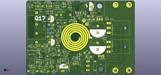
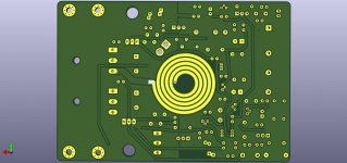
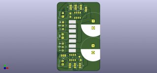
Since I just have time, another optimization related to the shortest board length from the radiator. If the original aluminum angle would have 28 - 30 mm inner length, then this design should work. I have also further optimized the ground and nostalgic trace curves, so that it also looks like an old PCB. 😀
The PCB for the active rectifier I have also drawn further. At the first attempt, still missing a ground contact of the electrolytic capacitor, I have overlooked. For this I have widened the traces to the maximum, so that current peaks can also be conducted to 35 um without heat generation.
The PCB for the active rectifier I have also drawn further. At the first attempt, still missing a ground contact of the electrolytic capacitor, I have overlooked. For this I have widened the traces to the maximum, so that current peaks can also be conducted to 35 um without heat generation.
Attachments
- Home
- Amplifiers
- Solid State
- Q17 - an audiophile approach to perfect sound