Hello,
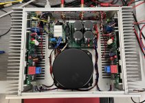
I tested the boards with a basic power supply at 58Vdc. Both heatsinks are connected to ground and the GND of the power supply is connected to ground via a 10R NTC and a ground breaker circuit (bridge+R+C).
No noise in the speakers (91dB sensibility). The grounding is good and the 50Hz is at a level that we can't hear. If I move the different cables, we do not hear a rise in hum. The boards seem immune to the wiring.
I will clean up the different files and publish the Q17-Turbo v2 on my Github this weekend if I have time.
Regards.
Stef.
Attachments

Last edited:

Hello,
I downloaded the files of the Q17-Turbo version 2.0.1 on the Github repository.
Regards,
Stef.
Version [2.0.1] (5-10-2024)
I downloaded the files of the Q17-Turbo version 2.0.1 on the Github repository.
Regards,
Stef.
Version [2.0.1] (5-10-2024)
- Complete new PCB design and components placement.
- Same PCB size, mounting holes and power transistor locations as v1.
- Removed all thermal brakes and VIAs.
- Now use same L1 coil as Q17-Mini.
- Merged GND / GNDPWR ground and built a new ground plane using GND zones and star topology.
- Added a dual footprint with lead spacing of 2.5mm and 5.0mm for C3 and C6.
- Removed R32 no longer needed due to the new ground plane.
- Updated C7 to 3.0uF.
- Added 2 diodes 1N4148 (D8/D9) for a more secure MOSFET protection.
- Added SOT-23 footprint for Q1 and Q4 on back PCB (Q1' = SI2328DS and Q4' = SI2325DS). Need 16V 1N5246B zener on D2 and D3 to get 14V. See Q17-Turbo-SMD-BOM.md file.
- Reduced hole size of resistors R26, R27 and R28.
- Replaced IXTH48P20P by IXTQ36P15P for Q16.
- Updated R17 to 150R for 1.2V sensibility (with LSK170B).
- Updated R15 and R35 to 270R for IXTQ36P15P compatibility.
- Replaced JFET choice OPA1641 by OPA828 (U1).
- Updated R10 and R13 to 8R2 for IXTQ36P15P compatibility. Bias for class A stage is now 78mA (+8mA).
- The board now consume at idle 220mA @ 60Vdc (warm board).
- Updated diagram with last components and values.
- Updated iBOM Q17-Turbo-BOM.html and Q17-Turbo-SMD-BOM.md files.
Can you mail me the price for both versions with shipping to Belgium ?
The mini boards are those an replacement for the original Quad 405 boards ?
The mini boards are those an replacement for the original Quad 405 boards ?
Hello StefI have 2 Turbo boards and 4 Mini boards left.
Stef.
Can You also send me PM with price of boards shipped to Poland
Hi Stef,
Would it be possible for you to add a zip archive for the LTSpice sim files in your git repository?
Regards
Alan
Would it be possible for you to add a zip archive for the LTSpice sim files in your git repository?
Regards
Alan
Hi Stef,
Would it be possible for you to add a zip archive for the LTSpice sim files in your git repository?
Regards
Alan
HI,
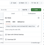
LTSpice files are here: https://github.com/stefaweb/Q17-Amplifier/tree/main/Q17-LTspice
The best way to bring back files from the Github repository is through the "code" menu.
Stef.
Attachments
Hello Stef
Can You also send me PM with price of boards shipped to Poland
Hi,
It depends on the weight. Up to 250g, it costs 14.25€ with signature. Postage is expensive in France.
Q17-Turbo PCB = 11€
Q17-Mini PCB = 5€
Stef.
Sorry, I no longer have Turbo PCB in stock.
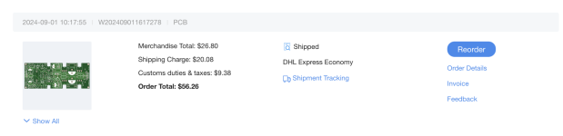
At https://jlcpcb.com, the price for 5 units is 56$.
For the Turbo, you need a lot of FQA46N15/IXTQ36P15P to match them by pair. May be 10/15 of each. Very expensive.
Stef.
At https://jlcpcb.com, the price for 5 units is 56$.
For the Turbo, you need a lot of FQA46N15/IXTQ36P15P to match them by pair. May be 10/15 of each. Very expensive.
Stef.
Attachments
Hi Stef,HI,
LTSpice files are here: https://github.com/stefaweb/Q17-Amplifier/tree/main/Q17-LTspice
The best way to bring back files from the Github repository is through the "code" menu.
Stef.
Thank you for the helpful tip. I was/am not very familiar with How Github works.
regards
Alan
Hello,
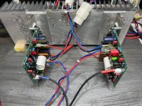
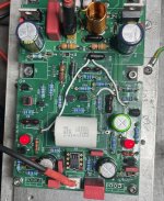
This picture shows just one of the many attempts I made to improve the Q17-Turbo ground plane. The PCB published on my Github does not require this kind of modification of course.
Stef.
This picture shows just one of the many attempts I made to improve the Q17-Turbo ground plane. The PCB published on my Github does not require this kind of modification of course.
Stef.
Stef ,
In the past I did get a tip from Hugh Dean ( Aspen Amps ) regarding the use of FQA/PF and IXTQ power FETs .
Solder a 470p and 47R resistor between drain and gate to avoid future problems which could happen due the high transduction of those FETs .
This way you slow them down a bit and protect too for the use in amps .
Last edited:
- Home
- Amplifiers
- Solid State
- Q17 - an audiophile approach to perfect sound