
Hello,
Some news about the PCB of the future Q17-Turbo v2.
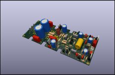
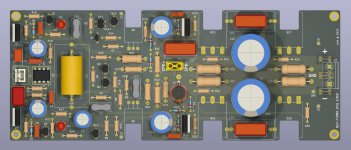
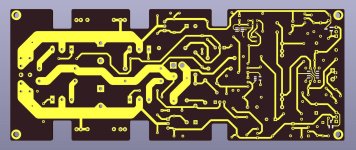
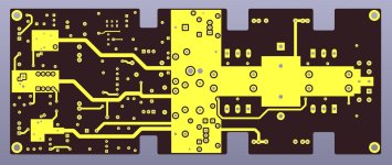
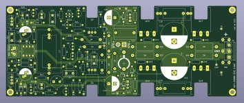
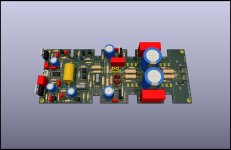
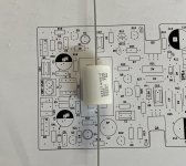
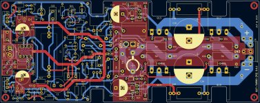
I worked on the ground plane on the top. This new ground plane should allow to remove R32 from the original schematic and to improve the SNR. I also added a double footprint for C3 and C6. We find less and less 47uF with 5mm pitch. I added the 2.5mm pitch. I also optimized the placement of the components everywhere above and below. I also put all the components to the correct size on the 3D model.
More in the next episode.
Regards,
Stef.
Some news about the PCB of the future Q17-Turbo v2.
I worked on the ground plane on the top. This new ground plane should allow to remove R32 from the original schematic and to improve the SNR. I also added a double footprint for C3 and C6. We find less and less 47uF with 5mm pitch. I added the 2.5mm pitch. I also optimized the placement of the components everywhere above and below. I also put all the components to the correct size on the 3D model.
More in the next episode.
Regards,
Stef.
Attachments
Hello,
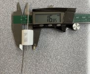
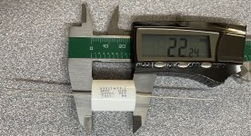
The other day, I told you about the existence of a 3uF MKP capacitor for C7. I finally cracked and ordered 2 for the future Turbo.
Cornell Dubilier - Film Capacitors POLY MET 100V 3uF - 935C1W3K-F
https://www.mouser.fr/ProductDetail/Cornell-Dubilier-CDE/935C1W3K-F?qs=BsPyPsHBXitmOy4GUpF/4Q==
They also fit in the Mini. Even better because they are shorter than the Vishay 2.2uF.
All that remains is to see what it will give in the circuit and when listening.
Stef.
Attachments
Hello,
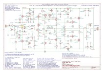
I started testing the first Q17-Turbo v2 prototype.
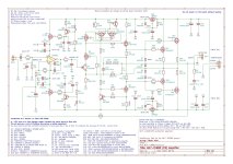
This prototype allowed me to adjust the circuit configuration and optimize the PCB. I changed some component values after testing and added the measurements on the diagram.
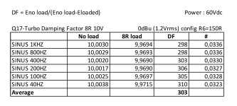
The specs are good and the power with the circuit configuration used will be 150W under 8R (with 60Vdc at input and 1.2V sensibility). It clip at 35Vrms.
I still have a lot of testing to do and some optimizations to try but it seems to be going well.
Regards,
Stef.
I started testing the first Q17-Turbo v2 prototype.
This prototype allowed me to adjust the circuit configuration and optimize the PCB. I changed some component values after testing and added the measurements on the diagram.
The specs are good and the power with the circuit configuration used will be 150W under 8R (with 60Vdc at input and 1.2V sensibility). It clip at 35Vrms.
I still have a lot of testing to do and some optimizations to try but it seems to be going well.
Regards,
Stef.
Attachments

Last edited:
Hi!
A pair of Vishay 100V mosfet.
Q1': SI2328DS
Q4': SI2325DS
With the SMD parts and 60V rails, zeners D2 and D4 MUST BE REPLACED by 16V 1N5246B zener to get 14V.
With the SMD parts, we get -3dB more on the 50Hz rejection.
I replaced Q6 with FQPF3N80C. With the Toshiba I got burst of oscillation > 32V. With the FQPF3N80C it's ok until the clip à 35V.
Stef.
Hello,
A quick call for advice.
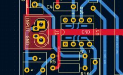
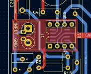
To optimize the input ground plane, I am hesitating between these two versions.
Version A with a ground plan under the op-amp is the current prototype version.
Version B is a version without the ground plane above the op-amp.
Which version would be preferable to minimize op-amp disturbances?
Regards,
Stef.
A quick call for advice.
To optimize the input ground plane, I am hesitating between these two versions.
Version A with a ground plan under the op-amp is the current prototype version.
Version B is a version without the ground plane above the op-amp.
Which version would be preferable to minimize op-amp disturbances?
Regards,
Stef.
Attachments
I'm trying to take maximum precautions against ground loops and op-amp pollution by ground coming from the input because I don't know yet what the Turbo v2 will give without R32. I haven't tested it in stereo yet with one PSU for both boards. Not before October. I'm missing parts to build two boards.
In the meantime, in mono, the Turbo works well. It's been running in real time for 2 days with background music on a speaker. Very good bass control. I think it should satisfy owners of speakers with a tortuous impedance.
In the meantime, in mono, the Turbo works well. It's been running in real time for 2 days with background music on a speaker. Very good bass control. I think it should satisfy owners of speakers with a tortuous impedance.
Hello!
I have published on my Github repository a maintenance version 3.0.3 of the Q17-Mini.
https://github.com/stefaweb/Q17-Amplifier/tree/main/Q17-Mini-3.0
Regards,
Stef.
Version [3.0.3] (14-09-2024)
I have published on my Github repository a maintenance version 3.0.3 of the Q17-Mini.
https://github.com/stefaweb/Q17-Amplifier/tree/main/Q17-Mini-3.0
Regards,
Stef.
Version [3.0.3] (14-09-2024)
- Reduced hole size for R26, R27, R28 and R31.
- Added a dual footprint with lead spacing of 2.5mm and 5.0mm for C3 and C6.
- Changed R15 to 270R.
- Modified ground plane connection for C2.
Hello,
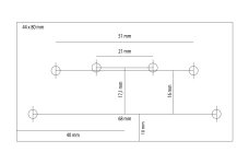
I found the time to make a drilling plan for the Q17-Mini v3 on an aluminum plate in Type-T Aluminum angle or Type-F Aluminum angle.
The minimum length to be able to place a board is 80mm and the plan of the aluminum roof is at least 44mm wide.
Have fun!
Stef.
I found the time to make a drilling plan for the Q17-Mini v3 on an aluminum plate in Type-T Aluminum angle or Type-F Aluminum angle.
The minimum length to be able to place a board is 80mm and the plan of the aluminum roof is at least 44mm wide.
Have fun!
Stef.
Attachments


Hello,
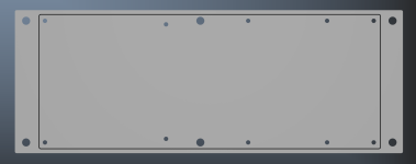
While waiting for the prototypes to progress, I prepared a mounting plate for the Q17-Turbo. It is 216 x 80 mm and 5 mm thick with 4 large holes for M4 screws (and 2 more holes in the middle if your plate bends a little). The other holes are tapped M3.
I made a .dxf file which is on my Github repository. I entered it on the site of a metal cutting seller. He swallowed it without flinching. 😉
To be tested.
Regards,
Stef.
Attachments

Last edited:
Hello,
I built both boards of the Q17-Turbo v2. It seems to work well in stereo.
I will let it run like this for a while. I still need to try it with a real power supply. For now, it is still connected to the lab power supply.
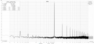
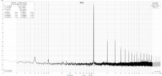
I made some modifications to the low level ground plane on the PCB to improve the 50Hz (or 60Hz) rejection. The 50Hz is now at -113dBu. The final version of the PCB will be v2.0.1.
Regards,
Stef.
I built both boards of the Q17-Turbo v2. It seems to work well in stereo.
I will let it run like this for a while. I still need to try it with a real power supply. For now, it is still connected to the lab power supply.
I made some modifications to the low level ground plane on the PCB to improve the 50Hz (or 60Hz) rejection. The 50Hz is now at -113dBu. The final version of the PCB will be v2.0.1.
Regards,
Stef.
Attachments
Me again.
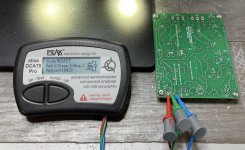
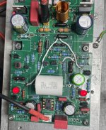
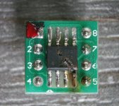
If you solder the mosfet Q1 and Q4 in SMD under the PCB, I advise you to test them immediately after soldering them. Be aware that if the smosfet are poorly soldered or non-functional, when switching on, you risk sending 50/55V directly into the opamp.
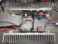
Another tip, always first test the board without the power transistors. If the board is functional, it draws around 11mA per rail. Then solder Q5 and Q6, the board should draw around 90/100mA per rail. With the 4 big mosfet, it should draw around 110/130mA per rail when warm. If when cold, you draw more than 250mA per rail, you have a problem with Q5/Q6 or the big mosfet.
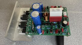
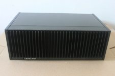
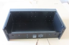
Some pictures of my various tests on the proto 2.0.
Stef.
In guest start, one of the opamps that I fried. 😈
If you solder the mosfet Q1 and Q4 in SMD under the PCB, I advise you to test them immediately after soldering them. Be aware that if the smosfet are poorly soldered or non-functional, when switching on, you risk sending 50/55V directly into the opamp.
Another tip, always first test the board without the power transistors. If the board is functional, it draws around 11mA per rail. Then solder Q5 and Q6, the board should draw around 90/100mA per rail. With the 4 big mosfet, it should draw around 110/130mA per rail when warm. If when cold, you draw more than 250mA per rail, you have a problem with Q5/Q6 or the big mosfet.
Some pictures of my various tests on the proto 2.0.
Stef.
In guest start, one of the opamps that I fried. 😈
Attachments


- Home
- Amplifiers
- Solid State
- Q17 - an audiophile approach to perfect sound