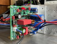
Hi Karsten!
For 2 pairs, the bias must be higher too.
In simulation with the original circuit and 1 pair, it seems that you have to put R10=R13=9R1. For 2 pairs, you will probably have to put more (maybe 8R2, 7R5, 6R4 or 6R2).
To adjust, I use 2 trimmers of 10R but you can also make resistors of 8R2 and 9R1 by assembling 2 resistors. It must be precise.
The driver transistors Q5/Q6 do not seem to have any impact on the spectrum.
I uploaded Q17-Power-Transistors-Selection-1.4.2 with the last test on Github.
Stef.
ps: use dBu for measurements, otherwise we can't compare.
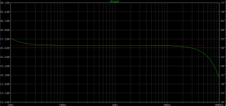
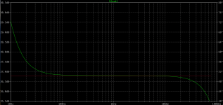
I forgot. If you rework your amp, take the opportunity to switch C7 to 2.2uF (or better 3uF, not standard) to have a flat bandwidth. With 1uF, you have an exaggeratedly high curve for frequencies from 20Hz to 500Hz.
Stef.
Stef.
Hello,
I was doing stereo tests of the new configuration.
I have 2 power supplies. With one it works well. No noise. With the second, it makes hum in the 2 speakers. Weird.
Here are the two power supplies:
The one that works: https://github.com/stefaweb/Q17-Amplifier/tree/main/Q17-PSU-MONO 1.0
The one that makes noise: https://github.com/stefaweb/Q17-Amplifier/tree/main/Q17-PSU-1.0.6
The toroid transformer is the same, a 2x35Vac 400VA.
I can't explain the cause at the moment.
Works fine in stereo with my lab PSU too.
Otherwise, the new FQA46N15 / IXTQ36P15P configuration works great in stereo.
Stef.
Attachments
Last edited:
The 10 Ohms with 2x FQA seams to work fine. Only with ITX there is a problem.Hi Karsten!
For 2 pairs, the bias must be higher too.
In simulation with the original circuit and 1 pair, it seems that you have to put R10=R13=9R1. For 2 pairs, you will probably have to put more (maybe 8R2, 7R5, 6R4 or 6R2).
To adjust, I use 2 trimmers of 10R but you can also make resistors of 8R2 and 9R1 by assembling 2 resistors. It must be precise.
The driver transistors Q5/Q6 do not seem to have any impact on the spectrum.
I uploaded Q17-Power-Transistors-Selection-1.4.2 with the last test on Github.
Stef.
ps: use dBu for measurements, otherwise we can't compare.
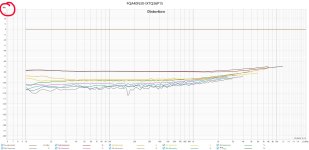
Why should I use dBu ? The problem is I have to max out the output from the soundcard and make the input to the soundcard as close to clipping as possible to get the lowest noisefloor and lowest distortion from the soundcard. The measurements shows a relation between fundamental and harmonics (and noise), so it is a relative measurement anyway. As long as I am stating the output level form the amp. It is always into 8 Ohms.
So the voltage level is 2,82 V RMS @1 Watt and 26,8 V RMS @ 90Watt.
I can of course use a Voltage to dBu converter , but why? 2.82 V rms is apparently 11.223 dBu... 1W into 8 Ohm makes more sense to me.
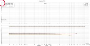
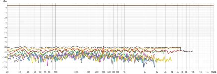
Latest measurements.
The original board with 2 sets of MOSFets should have 8,2 Ohms as R10 and R13 even with FQA36p15.
ITX and FQA are pretty much alike when using 8,2 Ohms.
@Stef Why are you recommending to increase C1 to 3-4 Uf? The frequency response is ruler flat all the way to 20Hz
The original board with 2 sets of MOSFets should have 8,2 Ohms as R10 and R13 even with FQA36p15.
ITX and FQA are pretty much alike when using 8,2 Ohms.
@Stef Why are you recommending to increase C1 to 3-4 Uf? The frequency response is ruler flat all the way to 20Hz
Attachments
-
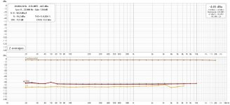 ITX STEPPED SINUS 1W 8,2 OHM.jpg194.1 KB · Views: 76
 -
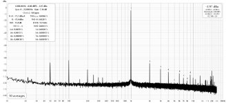 ITX RTA 1W 8,2 OHM.jpg204 KB · Views: 78
 -
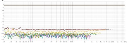 ITX DIST 1W 8,2 OHM.jpg169.3 KB · Views: 63
 -
 FQA STEPPED SINUS 1W 10 OHM.jpg192.1 KB · Views: 67
 -
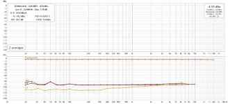 FQA STEPPED SINUS 1W 8,2 OHM.jpg194.4 KB · Views: 74
 -
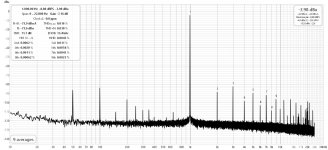 FQA RTA 1W 10 OHM.jpg205.2 KB · Views: 63
 -
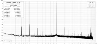 FQA RTA 1W 8,2 OHM.jpg203.3 KB · Views: 70
 -
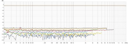 FQA DIST 1W 10 OHM.jpg167.9 KB · Views: 61
 -
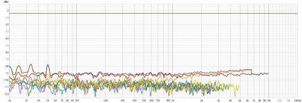 FQA DIST 1W 8,2 OHM.jpg168 KB · Views: 57
Hello,
Look a few pages back on the forum. I posted the REW curves with 1uF and 2.2uF for C7. It does it with the LTSpice file too.
2.2uF is the minimum. 3uF is ideal but a non-standard value. 3.3uF or 4.7uF are too strong.
Stef.
Look a few pages back on the forum. I posted the REW curves with 1uF and 2.2uF for C7. It does it with the LTSpice file too.
2.2uF is the minimum. 3uF is ideal but a non-standard value. 3.3uF or 4.7uF are too strong.
Stef.
Hello,
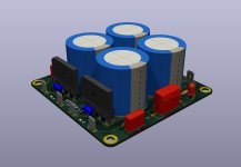
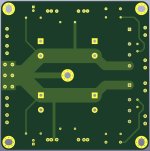
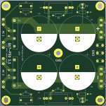
For those looking for a compact and simple filter board, I have remade the PCB of my dual bridge power supply. I have corrected the ground planes for better ground management when using it with two amplifier boards at the same time. The old PCB could generate hum under certain circumstances.
The files and Gerber are available here: https://github.com/stefaweb/Q17-Amplifier/tree/main/Q17-SIGMA-PSU-1.1
It is best to print this PCB in 2 Oz copper.
I haven't taken a picture of the new card yet.
Regards,
Stef.
Attachments
Last edited:
Hello everyone.
The Q17-Mini 3.0.2 is coming.
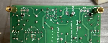
Two new features: optional SMD footprint for Q1/Q4 and two more diodes for power Mosfet protection.
I've been wanting to find a solution for a long time to no longer have these two big antennas on each side of the opamp. It's done. I tried various SOT-23 mosfets and selected a pair of SI2328DS and SI2325DS from Vishay Siliconix. In this case, zeners D2 and D4 must be replaced by 15V 1N5245B zener to get 13V.
I will put the files docs online in a few days.
Stef.
The Q17-Mini 3.0.2 is coming.

Two new features: optional SMD footprint for Q1/Q4 and two more diodes for power Mosfet protection.
I've been wanting to find a solution for a long time to no longer have these two big antennas on each side of the opamp. It's done. I tried various SOT-23 mosfets and selected a pair of SI2328DS and SI2325DS from Vishay Siliconix. In this case, zeners D2 and D4 must be replaced by 15V 1N5245B zener to get 13V.
I will put the files docs online in a few days.
Stef.
Attachments
Hello,
I downloaded the files for version 3.0.2.
https://github.com/stefaweb/Q17-Amplifier/tree/main/Q17-Mini-3.0
Have fun.
Stef.
Version [3.0.2] (23-08-2024)
I downloaded the files for version 3.0.2.
https://github.com/stefaweb/Q17-Amplifier/tree/main/Q17-Mini-3.0
Have fun.
Stef.
Version [3.0.2] (23-08-2024)
- Added 2 diodes SL1M-AQ (D8/D9) for a more secure MOSFET protection.
- Added SOT-23 footprint for Q1 and Q4 on back PCB (Q1' = SI2328DS and Q4' = SI2325DS). Need 15V 1N5245B zener on D2 and D3 to get 13V.
- Replaced IXTH48P20P by IXTQ36P15P for Q16.
- Replaced JFET choice OPA1641 by OPA828 (U1).
- Updated R10 and R13 to 8R2 for IXTQ36P15 compatibility. Bias for class A stage is now 78mA (+8mA).
- Moved Q7' SMD footprint closer to Q7.
- The board now consume at idle 200mA @ 50Vdc (warm board).
- Updated diagram with last components and values.
- Updated Q17-Mini-BOM.html and Q17-Mini-SMD-BOM.md files.
- Added Q17-Power-Transistors-Selection table on Github repository.
Last edited:
I forgot. If you rework your amp, take the opportunity to switch C7 to 2.2uF (or better 3uF, not standard) to have a flat bandwidth. With 1uF, you have an exaggeratedly high curve for frequencies from 20Hz to 500Hz.
Hello,
If you are looking for the ideal C7 capacitor for the Q17 (and which fits in the slot), I found at the bottom of the Mouser catalog this capacitor of 3uF 100V MKP from CDE. It is also available at Digikey.
It is not cheap but you will have the ideal bandwidth with this one.
https://www.mouser.fr/ProductDetail/5984-100V3-F
I also found another one that would be suitable but it is not available anywhere: Nichicon MPH1104300KE
There are other 3uf capacitors but they are huge and do not fit because they are designed for 400v or more.
Regards,
Stef.
Hi,
I have 3 different BS250. None of them are BS250p. Which one of these do you suggest I use? Could they be fake? I can't get Bs250P.

I have 3 different BS250. None of them are BS250p. Which one of these do you suggest I use? Could they be fake? I can't get Bs250P.
Hi!
The right transistor is:
BS250P
https://www.mouser.fr/ProductDetail/Diodes-Incorporated/BS250P?qs=OlC7AqGiEDnRUFCQhRDfhA==
The obsolete "BS250" will do not go as replacement and the pinout is not the same. The BS250P from Vishay do not have the same pinout too.
Stef.
The right transistor is:
BS250P
https://www.mouser.fr/ProductDetail/Diodes-Incorporated/BS250P?qs=OlC7AqGiEDnRUFCQhRDfhA==
The obsolete "BS250" will do not go as replacement and the pinout is not the same. The BS250P from Vishay do not have the same pinout too.
Stef.
Last edited:
You should check the spec with a transistor tester and compare.
The third one on the right in the photo looks good. It looks like the BS250P.
You may need to pair Q11 and Q111 transistors to have same Vbe or Vgs at 5mA. This improves the accuracy of the CCS+ current mirror.
The third one on the right in the photo looks good. It looks like the BS250P.
You may need to pair Q11 and Q111 transistors to have same Vbe or Vgs at 5mA. This improves the accuracy of the CCS+ current mirror.
Attachments
- Home
- Amplifiers
- Solid State
- Q17 - an audiophile approach to perfect sound
