
Hi,
New version of the voltages and consumption for the version 1.3.x of the Q17-Mini. I added more measures and corrected a wrong measure point.
Regards,
Stef.
Online PDF file.
https://github.com/stefaweb/Q17-Amp... Archives/Q17-Mini-schematic-1.3-measures.pdf
New version of the voltages and consumption for the version 1.3.x of the Q17-Mini. I added more measures and corrected a wrong measure point.
Regards,
Stef.
Online PDF file.
https://github.com/stefaweb/Q17-Amp... Archives/Q17-Mini-schematic-1.3-measures.pdf
Attachments
Hi,
I need to repair my Mini 2.0 prototype first. I burnt it. An error during measurements. I sent 2V at 20KHz sinus at input instead of 1KHz... Boom.
To be continued in the next episode.
Stef.
I need to repair my Mini 2.0 prototype first. I burnt it. An error during measurements. I sent 2V at 20KHz sinus at input instead of 1KHz... Boom.
To be continued in the next episode.
Stef.
Oh, I am so sorry about ... 2V is quite a big voltage ... I made some measurements earlier this morning with my older Quad 405-2 and I was using a tablet with a software which generates sinus from 2Hz to 30kHz ... and I started to play very very carefully, and hearing the signal in the loudspeakers. When I got to 18 kHz ... I started to turn up very very gently the volume potentiometer and watch the wave on an osciloscope while alse hearing, and at a certain point, the torroidal transformer (which is very undersized 150W per channel) started to buzz ... and immediately I turned back the volume. I have a 1000W battery of tweeters (10x100W each) connected in series/parallel and they absorb huge amps at 3,5Ohm rezistence of the entire connected 10 tweeters (Z is larger, obviously) but still ... and I measured 45Vac peak to peak (22,5V half sinus, 22,5V the other half sinus - all looking good so far) but the amps must be rised up crazy ... And I never exceeded 0,5V on input ...
which gain has this amplifier?
30.....40dB?
22,5Vpeak is about 16Volt rms --> so you put about 73WATT into 3,5Ohm load - current is I= U/R = 4,5Amps per rail !!!
that is the maximum of the transformer!!!-->
30.....40dB?
22,5Vpeak is about 16Volt rms --> so you put about 73WATT into 3,5Ohm load - current is I= U/R = 4,5Amps per rail !!!
that is the maximum of the transformer!!!-->
I have no ideea about the gain ... but it is using some chinese bipolars, low power, low amps ... so until I am not building the new Q17 Mini 2.0 I am very careful with listening music ... I could burn the tranzistors ... there is a risk. The transformer is another problem since it was design very poor ... maximum 3Amps ... it cannot deliver more then that. So the time has come for me to make an upgrade of my too old chinese Quad's. Also my speakers would need an upgrade ... I am still using second hands very old speakers.
hi moor
yes you are right...be carefully with that power amp. the transistors..if correct installed and cooled are not really a problem with power and heat.
yes it is no recommended to fully load your speakers until you are not sure that your amp is correct build.
please make a pause
then take your time and check all voltages which stef did on post 2262. it is important that you do that.
chris
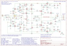
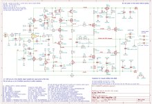
Hi,
The Q17-Mini 2.0 measures in schematic.
It is with 50V, without signal, without load at the output and with R32 = 10R.
By the way, I think it's better with a JEF150 in Q7.
Regards,
Stef.
Online version.
https://github.com/stefaweb/Q17-Amplifier/blob/main/Q17-Mini 2.0/Q17-Mini-schematic.pdf
The Q17-Mini 2.0 measures in schematic.
It is with 50V, without signal, without load at the output and with R32 = 10R.
By the way, I think it's better with a JEF150 in Q7.
Regards,
Stef.
Online version.
https://github.com/stefaweb/Q17-Amplifier/blob/main/Q17-Mini 2.0/Q17-Mini-schematic.pdf
Attachments
Thank you very much Stef ! ... so, it would be best to choose JFE150 as Q7 and what about choosing between BS250P, ZVP2106 and VP2206 N3-G ?
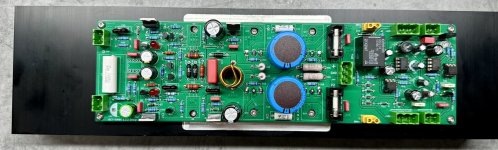
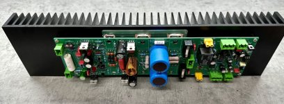
Hi everyone, my Q17 ist finally finished!

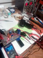
It was quite an odyssey to get there. In September I had finished soldering two working boards, but while testing on the bench, some clamp fell off and there must have been a short on the input or something. R15 ended up in smoke and somehow the board was so damaged by that, that I couldn't fix it anymore. (Silkscreen came off over the trace, etc.)
So I soldered a new board. Luckily they send you five. 🙂 On testing, only one half of the board turned on. After some analyzing with Tim, it turned out that one of the LEDs was DOA. So I changed the LED, but then there was only very distorted sound coming from that board. Something must have been damaged by turning on the board with the broken LED. We tried at lot of stuff, but in the end, nothing worked and we had to give up on that board too.
On to the third version of that channel... This time it finally worked! I could mount everything in the case an connect everything. Tested it on the bench, worked beautifully. Then I put in some cable ties, closed the case, put it in the rack, turned it on and was greeted with flash and smoke. I don't know what it was, but something must have caused a short and both R32s were completely pulverized. Tim calculated, that there must have been some 20 to 100 W across them.
So, I replaced the resistors, redid all the cabling, so that no really no bare copper can be seen anywhere and turned it on again. This time no smoke, but beautiful music!

(This is actually before redoing the cabling. I also changed the heatsinks of the left board.)
After some listening, I am completely satisfied now. It is quite a few notches better than my previous build. (A Symasym Black Beauty.) The most difference can be heard in the highs. They are crystal clear, with very good separation. All in all, clarity is outstanding. Very transparent.
Listening to music is a joy with the Q17. I wouldn't have thought it, but it's really noticeably better than before. (At least that's my perception. I haven't done any strict A/B testing with the old amp and probably won't. So it might just be subjective validation. But anyway, it sounds very nice. 🙂)
I've also got a new DIY DAC/streamer now, based on the PCM1794a, also designed by Tim. Together with that DAC it's really exquisite.

(Mostly DIY: Speakers, rack, two amps, H2 generator and the DAC.)
Thanks to all who contributed to this amplifier! Tibi, Stef and Tim. Also many thanks to Tim for supporting me during the build. It would have been much harder without.
It was quite an odyssey to get there. In September I had finished soldering two working boards, but while testing on the bench, some clamp fell off and there must have been a short on the input or something. R15 ended up in smoke and somehow the board was so damaged by that, that I couldn't fix it anymore. (Silkscreen came off over the trace, etc.)
So I soldered a new board. Luckily they send you five. 🙂 On testing, only one half of the board turned on. After some analyzing with Tim, it turned out that one of the LEDs was DOA. So I changed the LED, but then there was only very distorted sound coming from that board. Something must have been damaged by turning on the board with the broken LED. We tried at lot of stuff, but in the end, nothing worked and we had to give up on that board too.
On to the third version of that channel... This time it finally worked! I could mount everything in the case an connect everything. Tested it on the bench, worked beautifully. Then I put in some cable ties, closed the case, put it in the rack, turned it on and was greeted with flash and smoke.
I don't know what it was, but something must have caused a short and both R32s were completely pulverized. Tim calculated, that there must have been some 20 to 100 W across them.So, I replaced the resistors, redid all the cabling, so that no really no bare copper can be seen anywhere and turned it on again. This time no smoke, but beautiful music!
(This is actually before redoing the cabling. I also changed the heatsinks of the left board.)
After some listening, I am completely satisfied now. It is quite a few notches better than my previous build. (A Symasym Black Beauty.) The most difference can be heard in the highs. They are crystal clear, with very good separation. All in all, clarity is outstanding. Very transparent.
Listening to music is a joy with the Q17. I wouldn't have thought it, but it's really noticeably better than before. (At least that's my perception. I haven't done any strict A/B testing with the old amp and probably won't. So it might just be subjective validation. But anyway, it sounds very nice. 🙂)
I've also got a new DIY DAC/streamer now, based on the PCM1794a, also designed by Tim. Together with that DAC it's really exquisite.
(Mostly DIY: Speakers, rack, two amps, H2 generator and the DAC.)
Thanks to all who contributed to this amplifier! Tibi, Stef and Tim. Also many thanks to Tim for supporting me during the build. It would have been much harder without.
Thank you very much Stef ! ... so, it would be best to choose JFE150 as Q7 and what about choosing between BS250P, ZVP2106 and VP2206 N3-G ?Hi,
The Q17-Mini 2.0 measures in schematic.
It is with 50V, without signal, without load at the output and with R32 = 10R.
By the way, I think it's better with a JEF150 in Q7.
Regards,
Stef.
Online version.
https://github.com/stefaweb/Q17-Amplifier/blob/main/Q17-Mini 2.0/Q17-Mini-schematic.pdf
Umm question.. ? Why go through all the trouble to build a transistor circuit only to recieve it with an IC? isn't that sortof , ahem, weird? you build this elaborate transistor circuit and then the input stage is an ic.
They are all just tools in the box, choose according to requirements.
Thank you very much Stef ! ... so, it would be best to choose JFE150 as Q7 and what about choosing between BS250P, ZVP2106 and VP2206 N3-G ?
Hi Moor,
You can put whatever you want. This doesn't matter much especially since v2 with the NDC7003. On the other hand, I have not tested the VP2206.
Regards,
Stef.
Hi Stef,
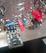
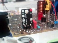
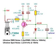
I started to built my first Q17 mini 2.0 ... and I made some modifications. And because I already tested that, I can show some photos. In order to power OPA1611 with precise +/-15V I replaced the Q1 and Q4 with LT3045 and LT3094. Did anyone tried this ? I am not sure if I'll hear any improvement but the second reason for this modification is that I might use the same voltage to power a preamp tone control also with OPA circuits, because LT can work ok up to 500 mA and one OPA is barely consuming few mA. Q3 and Q2 are surely capable of 100 mA.
I started to built my first Q17 mini 2.0 ... and I made some modifications. And because I already tested that, I can show some photos. In order to power OPA1611 with precise +/-15V I replaced the Q1 and Q4 with LT3045 and LT3094. Did anyone tried this ? I am not sure if I'll hear any improvement but the second reason for this modification is that I might use the same voltage to power a preamp tone control also with OPA circuits, because LT can work ok up to 500 mA and one OPA is barely consuming few mA. Q3 and Q2 are surely capable of 100 mA.
Attachments
this is a big question.Umm question.. ? Why go through all the trouble to build a transistor circuit only to recieve it with an IC? isn't that sortof , ahem, weird? you build this elaborate transistor circuit and then the input stage is an ic.
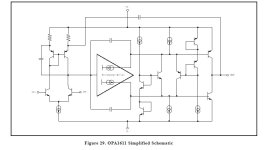
The operational amplifier itself has 2 amplification stages (see attachment), in addition, the output is made according to a common emitter circuit, and here a J-transistor is loaded onto the gate, which in general is not entirely logical, because to drive the J-fet you need voltage. Ok, next - Q1Q4 are not stabilizers for powering the microcircuit, since they do not have current feedback, so these vertical MOS transistors are only a current bypass for Q2 Q3. The OPA1611 has a current consumption of only 3.6 mA, i.e. any zener diode will do the job))).
R26R28 are an additional load for transistor Q5, worsening its linearity.
The current through coil L1 flows in the direction opposite to the operating current of the output stage Q15Q16, into the load, and this current is not compensated in any way.
The compensation bridge does not work here. The worse the bridge works, the better the sound will be amplified.
The circuit is very strange, /Therefore, to answer your question - why is there a microcircuit at the input?
answer: It will sound - the author likes it and it’s very cool!!!
Attachments
Last edited:
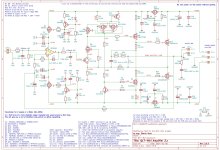
If you follow the authentic ideology of P. Walker, then the hybrid version of the circuit using mosfets looks like this in my understanding. There is an interesting nuance in Peter’s topology that gives a peculiarity of sound, and if you look at the spectrum of harmonics, only the 2nd dominates at all output power levels. I saw a similar spectrum of harmonics only on a tube amplifier.
I’ll post here a version of the topology without denominations so as not to interfere with the design of the author of the topic, you can simply compare the solutions. The scheme worked immediately, everything is stable, everything is in normal modes, perhaps in practice it will be possible to adjust the nuances.

P.S. "That any problem in audio engineering can be successfully addressed with "an equal mix of Ohm's Law and common sense" (с) Peter J.Walker
I’ll post here a version of the topology without denominations so as not to interfere with the design of the author of the topic, you can simply compare the solutions. The scheme worked immediately, everything is stable, everything is in normal modes, perhaps in practice it will be possible to adjust the nuances.
P.S. "That any problem in audio engineering can be successfully addressed with "an equal mix of Ohm's Law and common sense" (с) Peter J.Walker
Last edited:
Unlike the Q17, #2,279 doesn't use Walker's signature compensation of output stage distortion and thus is not Walker's "authentic ideology".
- Home
- Amplifiers
- Solid State
- Q17 - an audiophile approach to perfect sound