Regarding the LED's ... that might be related with a drop in voltages. I am thinking that, for example, if you have +50V on terminal 2 of Q13, then, according to measurements from the link, you'll have a stable +45V on terminal 3. The same is valid for the negative voltages, I presume. However, if there is a voltage drop (due to excessive amperage) on Q15,Q16 then, as the voltage drops to nearby 45V, then Q13 and Q14 may not transmit current towards Q2-D1. This might explain why LED's do not light up. LED's must have light even without Q2, or even if Q2 would be deffective. R2 is offering enough current to the LED.

In the 1.3 version boom list, R29 and R30 are 10K, in the scheme there are 100R. Which of these is correct?
I have no ideea. It would be best first, if possible for you, to test one module at a time, and disconnect Q15 and Q16 in order to see if there is too much voltage on terminals 2 of Q5 and Q6. If the voltage is too high, it is possible that the Idss on the Q5 and on the Q6 is higher than 70mA.
If you have a lab power supply with voltage and amps indicators, (I bought also for me here), you can measure and adjust from the pannel both the voltage output and read the amps consumption with 4 digits.
Let's say that you find out that the current Idss is 500mA. In this case, I assume that both R13 and R3 are having much higher voltages then indicated.
From what I could read extensively on these 123 pages of forum, the value of R3 can be adjusted (lowering it gently) until you get the correct voltages. But there is a catch ... all "mini" types schematics, below 2.0 are not having the latest enhancement by adding the excellent mirror current with NDC7003P (noted with U2 on Mini 2.0 schematic). Mini 2.0 does have it. This double-matched MOSFET is helping us to avoid matching Q9 and Q11 which is a difficult task and expensive.
But, if you are lucky, maybe a 20-40% adjustment of R3 may solve the problem for you. Maybe you should try this before trying matching Q9 and Q11.
Let me know about your progress.
I found something !! Look here https://www.diyaudio.com/community/...hile-approach-to-perfect-sound.374507/page-29
Open the file and see what happened in another case very similar to yours. Read pages 29 and 30.
Open the file and see what happened in another case very similar to yours. Read pages 29 and 30.
I replaced r29 and r30 with 100r. The problem continues. I cannot make measurements while there is power on the card. Q15 and Q16 heat up very quickly.
Disconnect Q15 and Q16 and verify everything up until there ... the other tranzistors won't heat so much. Take them out of the board and measure the voltages across R11 and R12 of 47 Ohms/2W.
There are two possibilities: a) the voltages are normal and the D1 and D4 LED's are start to light ok and ... b) voltages higher then normal which that means you might have a problem.
If a) is true then Q15,Q16 are defective. If b) is true, then the search continues (which does not exclude Q15,Q16 as being defective).
I read on this forum about buying official authentic tranzsitors but many as DAO (death at arrival). And this things scares me also because I didn't start yet my project. I am only studying the matter and I read of so many problems ... but this one scares me a lot because the tranzistors are expensive.
And there are other calculations which nobody seems to solve them properly with a formula, for choosing the correct gate rezistors (R14 and R15)
Don't give up ! Today is another good day for working on the problem.
Moor
I replaced r29 and r30 with 100r. The problem continues. I cannot make measurements while there is power on the card. Q15 and Q16 heat up very quickly.
Hi,
Happy New Year everyone.
Sorry but at the moment, I am not available to come to the forum.
For R29/R30 the correct value is 100R. This is the value that causes the least "plop" in the speaker when you turn off the power supply. 10K also works but causes more powerful noise in the speakers. If you have an HP protection circuit after the Q17 card, it doesn't matter.
Best regards,
Stef.
EDIT : for your power/led problem. Unsolder Q5/Q6 and test the low signal part of the circuit and the various voltage.
Hello, I may not have been asked, but just for clarification: If the LEDs aren't lighting up but the power MOSFETs are getting hot, there's a strong suspicion that Q15 and Q16 may be faulty. Have you measured these MOSFETs before soldering them in? Since the amplifier starts playing at around + - 30V, the power supply voltage of + - 40V is not a relevant factor.Hi Stef,
Give it on your advice: I had 1.3.1 pcb and psu pcb's made.psu voltage +-40dc
I Use
Q1-Q13:IRF610
Q2-Q10 2SA970
Q3-Q7 2SC2240
Q4-Q14 IRF9610
Q9-Q11 BS250 (There are two different cases of BS250 in stock. I tried both of them.)
Q5 IRF610
Q6 IRF9610
Q8 2N7000
Q12 2SC2240
Q15 IRFP240
Q16 IRFP9140
I couldn't get the circuit to work. The LEDs do not light up. IRFP240-9140 overheats in a short time. Can you help me where am I making a mistake?
First, you should measure the resistance between + Power and Line out, as well as - Power and Line out, without the modules being connected. Before taking the measurement, discharge the capacitors using a metal object. During the resistance measurement, the reading should increase as the capacitors charge.
Tim
hi
i am a silent reader here...because this project is in my building chain.
please be aware of dis - charge caps with bigger capacity! just with a metal screw driver or so..
if you have 50V or more rail (e.g. 60V) or so you should do with a big resistor like 10-20ohms and isolated ends and dis charge the cap over this resistor.
do not touch the ends of this discharge resistor because you will get 50Volt or more over your hands or your body !!
please keep in mind that a Voltage with 50VDC (+/- 25V rail !!!) is hurting your health!!
I think that's a Turkish flag.He's from China, unfortunately high risk of fake sand...
Oh yes, my bad, it's too small on my phone... 
That being said, fake sand is on every corner nowadays!
That being said, fake sand is on every corner nowadays!
Hi Tim.Hello, I may not have been asked, but just for clarification: If the LEDs aren't lighting up but the power MOSFETs are getting hot, there's a strong suspicion that Q15 and Q16 may be faulty. Have you measured these MOSFETs before soldering them in? Since the amplifier starts playing at around + - 30V, the power supply voltage of + - 40V is not a relevant factor.
First, you should measure the resistance between + Power and Line out, as well as - Power and Line out, without the modules being connected. Before taking the measurement, discharge the capacitors using a metal object. During the resistance measurement, the reading should increase as the capacitors charge.
Tim
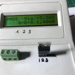
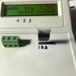
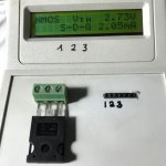
Thank you for your help. q15 and q16 have never been used. I used it here for the first time. Its originality is doubtful. Where should I take measurements? Which values should I read? Is there a picture showing the measurement points and measurement values? There is an image on Github but it cannot be read..
Hi fazil,
Maybe you can use this 30V voltages version
https://www.diyaudio.com/community/...hile-approach-to-perfect-sound.374507/page-46
It is better to start some trials at lower voltages. They here clearly shown on the schematic
Maybe you can use this 30V voltages version
https://www.diyaudio.com/community/...hile-approach-to-perfect-sound.374507/page-46
It is better to start some trials at lower voltages. They here clearly shown on the schematic
First of all, I would like to thank all of you for your interest and help.
I removed the Q5-6-15-16 mosfets. I checked them with both a tester and a multimeter. They look solid. When the MOSFETs are not on, the LEDs are on.
I checked the values and directions of all resistors, diodes and capacitors. All are normal. I made measurements according to the table on page 107. Most of the values do not hold. I'm leaving it for now. I can't deal with it. I don't have time.
Attachments
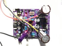
Just curious, did you properly electrically insulate all the mosfets from the aluminum heatsink?
And use plastic shoulder washers for the TO-220 fets?
Also, I wouldn’t trust kapton tape as an insulator, any sharp metal burr from all the holes in that aluminum plate would surely create a short.
And use plastic shoulder washers for the TO-220 fets?
Also, I wouldn’t trust kapton tape as an insulator, any sharp metal burr from all the holes in that aluminum plate would surely create a short.
Hi Vunce
I checked all the MOSFETs in contact with the cooler before applying electricity. There is absolutely no contact.
I checked all the MOSFETs in contact with the cooler before applying electricity. There is absolutely no contact.
I see on the photo that you have used TL071 as U1 Oamp ... verify if that one really fit ok in the schematics, because this one have been used in the older 2010 Quad-2 version schematics. Try to change that with one of the recommended... anyway, I am sorry for your loss.
Ok ... well, ... I am out of any ideas ... but your experience helped me also because seeing all this you have described made me to approach another method when my time will come to solder the components on the board. I'll do that with often checking on sections, and apply voltages and made measurements, for example ... instead of soldering everything at once, I'll do in 7 stages of soldering and testing components:
3. Test Q1,Q4 at 18V in series with 100 Ohm - and 400 mA load to be sure it does the job.
4. Q1,Q4 tests together with Q2 and Q3 and 45V supply.
5. Test Q13, Q14 at 50-55Vdc, to check if it gives constant 45V
6. Test Q1,Q4 and Q2,Q3 in series with Q13-Q14 powered at 50-55Vdc
7. Test OPA1611 + Q1,Q4 and Q2,Q3 in series with Q13-Q14 fed at 50-55Vdc and measure the output at the free end of R1=2.7k (give a signal and see how it looks).
8. Fit everything else except Q15,Q16 and measure without signal the voltages on the free terminals of R14,R15 at idle. The consumption should not be more than 80-90 mA.
9. A low level audio test can be done. If it sounds bad or overheats transistors Q5,Q6 then the scheme will not work.
10. Test Q15,Q16 separately with the previously detected gate voltages. The idle current consumption should be even much lower.
11. Start the assembly at idle. The maximum power consumption per power supply branch does not exceed 100mA (10W power dissipation at idle).
So, I'd rather solder components in 100 hours of work and voltages tests, then solder at once everything, then power on ... and see it start to smoke
- Home
- Amplifiers
- Solid State
- Q17 - an audiophile approach to perfect sound