The signature feature of the Walker amplifier was not the bridge, but the output power stage on transistors of the same conductivity, the bridge was needed to create a countercurrent across the coil, because bipolar transistors were used that were controlled by this current.Unlike the Q17, #2,279 doesn't use Walker's signature compensation of output stage distortion
The lower transistor was controlled through the emitter of the driver composite transistor of the lower output link cascade.
In a complementary topology, the bridge loses its efficiency, and when using mosfets (side) the bridge is an additional link to add distortion, because the mosfets are voltage controlled.
In the case of using power mosfets of the same conductivity, the lower link is controlled through the base of the Q8 bipolar transistor (attachment my post); to control through the base, it is not necessary to create a large countercurrent, therefore attaching the bridge in the famous “diamond” form is already an attavism. The initial current of mosfet power transistors cannot be 60 milliamps or lower, because the internal capacitance with analog control will not allow it to open quickly.
Peter was a musician - saxophone and flute, he would never do a complementary outpute stage, because he needs a clean second harmonic, and not a "forest" of odd harmonics from a complementary output stage.
Repeated attempts over the past 40 years to connect an output stage with transistors of different conductivity to the Quad, during listening, revealed a loss of the signature sound.
Utter nonsense - and a complete opposite of what you advocated just 18 months ago. Read Walker's article (attached) and stop hijacking other people's threads.
@iTiberius - apologies for these offtopic posts.
@iTiberius - apologies for these offtopic posts.
Attachments
Last edited:
Have you read this article yourself?Utter nonsense - and a complete opposite of what you advocated just 18 months ago.Read Walker's article (attached)
Look in the attachment why the 47 ohm resistor is included behind the coil, and why it turns out to be a bridge.

Thank you.apologies for these offtopic posts.
in the case of a complementary output stage, the initial current through the generator sets the current through the bases of transistors Tr1 Tr2 bypassing the coil Z4, the current is alternating with odd harmonics. Those. the bridge coil also requires an initial current to operate with minimal distortion. This is what Walker came up with "initial current through the bridge coil", and "few people still" mistakenly think that a coil in a bridge without additional initial current will perform high-quality current dumping.

the principle of “current dumping” itself was known a very long time ago, this equation was derived by the mathematician Bouchereau, but was not used in amplifiers due to the fact that a coil without an initial current generates large distortions, so in a "Thiel coil" it is shunted with a low-resistance resistor, just as B E transitions are shunted with a resistor in transistor output stages operating in class B or C.
the principle of “current dumping” itself was known a very long time ago, this equation was derived by the mathematician Bouchereau, but was not used in amplifiers due to the fact that a coil without an initial current generates large distortions, so in a "Thiel coil" it is shunted with a low-resistance resistor, just as B E transitions are shunted with a resistor in transistor output stages operating in class B or C.
Last edited:
Distortion spectra in comparison with the type of output stage, complementary with a bridge without an initial current through the coil and without a bridge where the coil is shunted by a resistor.

I specifically used different implementations of the output stages so that they differed from the author’s design of this topic and our opinions did not intersect. those who need it can independently check the “initial current of the dumping coil”.
I specifically used different implementations of the output stages so that they differed from the author’s design of this topic and our opinions did not intersect. those who need it can independently check the “initial current of the dumping coil”.
Last edited:
Hey guys,
I'll need major help as I'm unable to find quite a few parts from mouser or element 14.
List-
1) U2
2) Q5
3) Q6
4) Q7
5) Q8
6) Q9
7) Q15
8) Q16
Is there any list of alternative parts for this?
Also I'm new to the field of audio.
Thanks
Amit
I'll need major help as I'm unable to find quite a few parts from mouser or element 14.
List-
1) U2
2) Q5
3) Q6
4) Q7
5) Q8
6) Q9
7) Q15
8) Q16
Is there any list of alternative parts for this?
Also I'm new to the field of audio.
Thanks
Amit
Hi,
You will find parts equivalence on my repository on the Q17 diagram.
https://github.com/stefaweb/Q17-Amplifier
Regards,
Stef.
You will find parts equivalence on my repository on the Q17 diagram.
https://github.com/stefaweb/Q17-Amplifier
Regards,
Stef.

Hi,
It's weird. If I click on the basketball that I saved in my Github repository, everything is available.
Order Q17-Mini-2.0-BOM on Mouser
It's weird. If I click on the basketball that I saved in my Github repository, everything is available.
Order Q17-Mini-2.0-BOM on Mouser
Firstly thanks a ton for replying and helping me @stef1777. Please bear with me I’m very new to this a pure amateur to be honest.
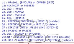
I have attached the list below of alternatives below, the question I have is are the ones that I’ve circled in pair in the sense if I use IXFH50N85X @Q15 should I be using IXTH48P20P @Q16.
The reason for this question is the power of both do not match in the data sheet. Also same doubt with FQPF7P20 @ 2SK3564 respectively.
Thanks
Amit
Attachments
Good morning,
Power is not the important parameter of power mosfet for it to be compatible. Personally, I have not tested all of these equivalences given by iTiberius because I run with my stock of original components. In the batch, I just tested the 2SK3564. It works with the Q17.
Stef.
Power is not the important parameter of power mosfet for it to be compatible. Personally, I have not tested all of these equivalences given by iTiberius because I run with my stock of original components. In the batch, I just tested the 2SK3564. It works with the Q17.
Stef.
Hello everyone,
I'm launching a design competition for the Q17.
Namely modify the input circuit to switch it to symmetrical TRS (4v or 4.5v) while keeping the possibility of using it in asymmetrical RCA 2V (without losing dBs).
To your pencils. 😉
Stef.
I'm launching a design competition for the Q17.
Namely modify the input circuit to switch it to symmetrical TRS (4v or 4.5v) while keeping the possibility of using it in asymmetrical RCA 2V (without losing dBs).
To your pencils. 😉
Stef.
I used the same components as in the BOM excluding power transistors where I use the original ones (FQA/FQP). You can use others brands of components for resistors or capacitors. The Q17 does not seem sensitive to this kind of change.
Regards,
Regards,
Hi Stef,
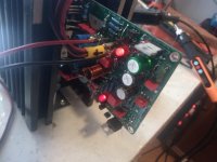
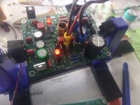
I have tested my first board just minutes ago and I think it could be useful my testimonial for other fans who wish to DIY.
Because I have a lab power supply, I could watch and observe the behaviour of Q17 Mini 2.0 at different voltages, up to 59V+/-.
Here is what I have observed while testing in several steps:
1) Powering only the OPA1611 with the help of Q1,2,3,4,13,14 and the 2 LEDs, the total current was 14 mA, out of which 10 mA for LED and 4 mA for the OPA (on both rails, the same amps value). Tested ok, audio ok. I just wanted to be sure it was not DOD or soldering too much. Tested all ok.
2) Powering everything at 50Vcc with no signal, and R32 strapped, one speaker connected, the total current per rail was 80 mA and this value was for maintaining the pre-finals Q5,6 within a low conductive state (as the bipolar transistors former Quad 405). Total power dissipation per rail is 4 W.
3) Powering everything at 59Vcc with no signal, and R32 strapped, one speaker connected, the total current per rail was 88 mA and power dissipation per rail is 4,4 W which is in normal range, less then 10W as specified ... it just couldn't be better ...
4) At 50Vcc all voltages are exactly as indicated in the schematic you provided me. Most impressive, V accross R3 and R13 is exactly including the third decimal ! ... At 50Vcc all voltages are slightly increased but those accross R3,R13 only the 3rd decimal is increased a little. I am amazed how stable this schematic is and how it is automatically adjusting everything without the need of any variable trimer.
Because most of the mosfets originally suggested in the schematic are no longer available, I used with great success the following:
Q5 IRF9630PBF 74W 800mOhm x 6,5A x 200V
Q6 IRF620PBF 50W 800mOhm x 5,2A x 200V
Q15 IXTQ50N20P 360W Enhancement N 60 mOhm x 50A x 200V
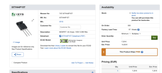
Q16 IXTH44P15T 300W Enhancement P 65 mOhm x 44A x 150V
Because I had presumed that in the near future these too might go obsolete, I bought from Mouser, everything for the 4 motherboards. But I still need 2 more for making a complete 5.1 audio. All other transistors remained those from the original schematic and they won't go obsolete too soon. So, because I tested these 4 new in combination, the information has value for those who are starting this adventure.
Further tests I'll make in the following days and then I'll continue to solder the remaining 3 boards. I used PCBWay for a full 15 boards order because maybe in the future I'll continue to upgrade the remaining Dolby Atmos 16 channels installation. For the moment I'd be just ok in doing the upgrade for the first 5.1 main channels. Most of the movies and/or concerts are in 5.1 format.
I have tested my first board just minutes ago and I think it could be useful my testimonial for other fans who wish to DIY.
Because I have a lab power supply, I could watch and observe the behaviour of Q17 Mini 2.0 at different voltages, up to 59V+/-.
Here is what I have observed while testing in several steps:
1) Powering only the OPA1611 with the help of Q1,2,3,4,13,14 and the 2 LEDs, the total current was 14 mA, out of which 10 mA for LED and 4 mA for the OPA (on both rails, the same amps value). Tested ok, audio ok. I just wanted to be sure it was not DOD or soldering too much. Tested all ok.
2) Powering everything at 50Vcc with no signal, and R32 strapped, one speaker connected, the total current per rail was 80 mA and this value was for maintaining the pre-finals Q5,6 within a low conductive state (as the bipolar transistors former Quad 405). Total power dissipation per rail is 4 W.
3) Powering everything at 59Vcc with no signal, and R32 strapped, one speaker connected, the total current per rail was 88 mA and power dissipation per rail is 4,4 W which is in normal range, less then 10W as specified ... it just couldn't be better ...
4) At 50Vcc all voltages are exactly as indicated in the schematic you provided me. Most impressive, V accross R3 and R13 is exactly including the third decimal ! ... At 50Vcc all voltages are slightly increased but those accross R3,R13 only the 3rd decimal is increased a little. I am amazed how stable this schematic is and how it is automatically adjusting everything without the need of any variable trimer.
Because most of the mosfets originally suggested in the schematic are no longer available, I used with great success the following:
Q5 IRF9630PBF 74W 800mOhm x 6,5A x 200V
Q6 IRF620PBF 50W 800mOhm x 5,2A x 200V
Q15 IXTQ50N20P 360W Enhancement N 60 mOhm x 50A x 200V
Q16 IXTH44P15T 300W Enhancement P 65 mOhm x 44A x 150V
Because I had presumed that in the near future these too might go obsolete, I bought from Mouser, everything for the 4 motherboards. But I still need 2 more for making a complete 5.1 audio. All other transistors remained those from the original schematic and they won't go obsolete too soon. So, because I tested these 4 new in combination, the information has value for those who are starting this adventure.
Further tests I'll make in the following days and then I'll continue to solder the remaining 3 boards. I used PCBWay for a full 15 boards order because maybe in the future I'll continue to upgrade the remaining Dolby Atmos 16 channels installation. For the moment I'd be just ok in doing the upgrade for the first 5.1 main channels. Most of the movies and/or concerts are in 5.1 format.
Attachments
-
 prima pornire IMG_20240407_133332.jpg306 KB · Views: 117
 -
 prima pornire IMG_20240407_133312.jpg335 KB · Views: 115
 -
 prima pornire 59Vcc IMG_20240407_133312.jpg92.9 KB · Views: 124
 -
 montaj fara finali IMG_20240405_134058.jpg307 KB · Views: 111
 -
 montaj fara finali IMG_20240405_134047.jpg391 KB · Views: 128
Great Moor !!
Have you checked the board with a scope?
If ok, I will add these parts to the transistor list.
Stef.
EDIT: I've the same PCB stand than you. 😉
Have you checked the board with a scope?
If ok, I will add these parts to the transistor list.
Stef.
EDIT: I've the same PCB stand than you. 😉
Last edited:
Not yet, but I'll do some oscilloscope tests during next days ...
I also would need to increase my trafo power from 100W per channel to 300W per channel ... it just does not offer the amps as it should, because even when listening to normal medium power in an appartment, peak signals are beyond 100W ... 15-18 kHz music signals often are beyond 200-250W and the trafo is just not doing good job. Already capacitors are 60 miliF per rail but if the trafo is not capable, then capacitors cannot help much. That will cost me a lot of money ... but ... that is the only way.
I also would need to increase my trafo power from 100W per channel to 300W per channel ... it just does not offer the amps as it should, because even when listening to normal medium power in an appartment, peak signals are beyond 100W ... 15-18 kHz music signals often are beyond 200-250W and the trafo is just not doing good job. Already capacitors are 60 miliF per rail but if the trafo is not capable, then capacitors cannot help much. That will cost me a lot of money ... but ... that is the only way.
The transformer is extremely important as you may have noticed with my setbacks and a poor quality transformer in the previous pages. 😉
I just regret not having had a 4x transformer made to have a double mono.
Bad new for the IXTH44P15T.
Stef.
I just regret not having had a 4x transformer made to have a double mono.
Bad new for the IXTH44P15T.
Stef.
Attachments
Last edited:
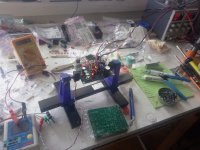
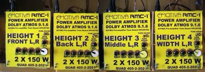
for my Atmos 16 channels I designed 8 trafos and 8 separated stereo modules in metalic boxes, but the first 8 channels from the Atmos system must be of very good quality. The next 4 are of medium importance and the last 4 actually very few sound can provide, because commercially, most users are having cheap decoders, up to 11.1 channels so most of the BD are coded with 12(11.1) out of 16 channels (15.1) in order to "fit" to a majority. Decoders of 15.1 or more might be very expensive.
Regarding the trafos, I already designed them to offer two secondaries [36-0-36 x2] and I was unsuccesful in building a good ideal rectifier but I am planning to build a highly advanced stabiliser from 65 to 59V (dual rail) for each module separately. And I have a modified Sigma22 schematic, and motherboard from Ali Express (full kit). This will do the job, no matter the rectifier is.
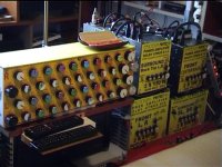
I can show you some photos ... my entire room is sorrounded by speakers.
Regarding the trafos, I already designed them to offer two secondaries [36-0-36 x2] and I was unsuccesful in building a good ideal rectifier but I am planning to build a highly advanced stabiliser from 65 to 59V (dual rail) for each module separately. And I have a modified Sigma22 schematic, and motherboard from Ali Express (full kit). This will do the job, no matter the rectifier is.
I can show you some photos ... my entire room is sorrounded by speakers.
Attachments
-
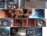 aranjamentul boxelor.jpg238.4 KB · Views: 140
 -
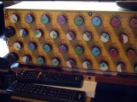
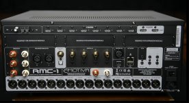 emotiva back panel.jpg232.8 KB · Views: 167
 -
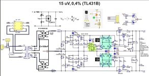 Sigma22 Dual Voltage Linear Power Supply 2x48V 30A bis.jpg285.6 KB · Views: 210
 -
 toate modulele.jpg470 KB · Views: 186
 -
 vlcsnap-2022-03-05-11h06m30s078.jpg112.6 KB · Views: 145
 -
 vlcsnap-2022-03-05-11h06m43s593.jpg104.4 KB · Views: 134
 -
 vlcsnap-2022-03-05-11h07m31s984 copy.jpg236.7 KB · Views: 145
Impressive amount of button. 😉
I have never tried this type of PSU. Is it fast enough?
There are lots of different sigma22 models on Aliexpress, which PCB did you choose?
Stef.
I have never tried this type of PSU. Is it fast enough?
There are lots of different sigma22 models on Aliexpress, which PCB did you choose?
Stef.
- Home
- Amplifiers
- Solid State
- Q17 - an audiophile approach to perfect sound