Here is the PCB from ali express: https://www.aliexpress.com/item/100...order_list.order_list_main.173.21ef1802J5ypnN
Here is the original Sigma22 https://www.amb.org/audio/sigma22/
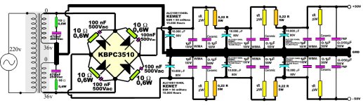
However, I modified the schematic replacing the normal zenner with TL431B and the minischematics in yellow collor (a transistor and some resistors around TL431B, but I did not tested nor it soldered yet ... I am busy with the Mini 2.0 boards. I also included in the modification the possibility to add up to maximum 65V+/- input and get 59V+/- output, in order to match my needs.
In the schematic posted above, it can be used one single rectifier with normal diodes ... not necessary for MUR820.
Here is the original Sigma22 https://www.amb.org/audio/sigma22/
However, I modified the schematic replacing the normal zenner with TL431B and the minischematics in yellow collor (a transistor and some resistors around TL431B, but I did not tested nor it soldered yet ... I am busy with the Mini 2.0 boards. I also included in the modification the possibility to add up to maximum 65V+/- input and get 59V+/- output, in order to match my needs.
In the schematic posted above, it can be used one single rectifier with normal diodes ... not necessary for MUR820.
Last edited:
The board is very large. Not easy to fit into a chassis.
Keep us posted on your tests. We can make a PCB if it works well. At AMB it has a v3 PCB with some modifications, in particular a double output to connect 2 amp boards.
Stef.
Keep us posted on your tests. We can make a PCB if it works well. At AMB it has a v3 PCB with some modifications, in particular a double output to connect 2 amp boards.
Stef.
It would be wonderful if you could make a smaller PCB for the Sigma22 and also to include the new modifications, but I'll need to test them before that and yes I'll keep you updated. My rectifier-filter as it is now, have been assembled in a separate metal box inside the bigger box, also the trafo is in separate metal box. So, Sigma 22 would need another metal box, placed between rectifier-filter and the Q17 module.
Attachments
It would be possible if we remove some of the heatsink and replaces some TH components with SMD. For less than 200mA (one Q17 module), maybe we don't need all that.
Here are all the Ali models I found:
https://fr.aliexpress.com/item/1005005048065175.html
https://fr.aliexpress.com/item/1005002134667580.html
https://fr.aliexpress.com/item/1005002434297131.html
https://fr.aliexpress.com/item/1005003725722757.html
Not found 3.0 PCB as AMB.
Stef.
Here are all the Ali models I found:
https://fr.aliexpress.com/item/1005005048065175.html
https://fr.aliexpress.com/item/1005002134667580.html
https://fr.aliexpress.com/item/1005002434297131.html
https://fr.aliexpress.com/item/1005003725722757.html
Not found 3.0 PCB as AMB.
Stef.
Why not buy the official Sigma22 from AMB instead of supporting copycats?

I think it would be best that on the PCB should not be included the two big electrolitic capacitors, the heatsinks and the rectifier. I already enclosed those in a separate box. What is missing from all chinese modules (except one) is the TL431B which is the best voltage reference to my knowledge. They used a normal zenner. However, for input voltages higher then 36V+/- the TL431B need an intermediate circuit with BC546B, R1,R3,R2,R4,R5 and R6 and in order to test this, I'll solder them on a very small 1cm board and connect it with 3 wires on the Sigma motherboard, because you need to keep 11,55V on the base of Q7. Also, on the chinese version there are missing D8-D11, D6,D7 and some of the 100nF/100V WIMA capacitors. But, for testing is ok to add them on the back side and see if everything works ok. But I promise I'll let you know as soon as I get there these days.
Why not buy the official Sigma22 from AMB instead of supporting copycats?
A kit from Chinese for the components and an official PCB from AMB. The best of the two words. 😉
If it works at 50V/60V, I would try to make a PCB where everything fits in 100x100mm as my regular PSU.
Stef.
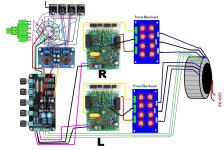
EDIT : @Moor, don't use CRC PSU with Q17 as in your drawing.
Last edited:
I'll short the CRC filter after I am finalising the first Sigma22 ... you are correct, the rezistor series induce voltage dropout.
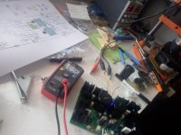
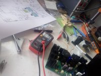
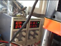
However I have some good news for you Stef, here are the testing Sigma22 up to 44Voutput, 49Vinput. I have increased the zenner up to 15V, just a normal zenner, which means, I can get more output voltage if I deliver more input, but for that, I have to desolder all the capacitors as they are rated at exactly 50Vdc. And then, I can test again, from 65V toward 59V and see if that works. But this test as I present here is very encouraging.
However I have some good news for you Stef, here are the testing Sigma22 up to 44Voutput, 49Vinput. I have increased the zenner up to 15V, just a normal zenner, which means, I can get more output voltage if I deliver more input, but for that, I have to desolder all the capacitors as they are rated at exactly 50Vdc. And then, I can test again, from 65V toward 59V and see if that works. But this test as I present here is very encouraging.
Attachments
rezistor series induce voltage dropout.
Not only this. With a CRC psu, you also increase the impedance of the power supply. Class Bs amps don't like this.
You must try the sigma22 power supply with a load of at least 200mA (both rails at the same time) to see if it is stable and what the measurements give in this case.
Afterwards, you also have to listen to it to see. Especially check if the bass are good. A bit like when you try a classic PSU and an SMPS. The SMPS works fine with a Class A or D amp but not very well with a Class B amp. This is normally quite easy to hear.
Maybe you could open a dedicated Topic like "Sigma22 PSU design at 60V". This may be of interest to other people and attract other people who know about sigma22 psu.
Stef.
Last edited:
Hi Stef,
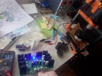
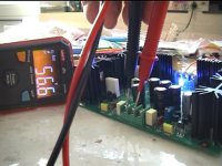
I had just tested input voltage 62V output (the maximum from my dual lab power supply) 56V ... next I'll test the 200 mA amps test and see if it is stable ... as you said. Proof attached. So it works with a 15V zenner ... so then I can make the modifications for TL431B. It is exactly 4 to 5 volts between input and output will be just fine for eliminating the ripple at high bass power ... if proven stable ... more tests will come tomorrow.
I had just tested input voltage 62V output (the maximum from my dual lab power supply) 56V ... next I'll test the 200 mA amps test and see if it is stable ... as you said. Proof attached. So it works with a 15V zenner ... so then I can make the modifications for TL431B. It is exactly 4 to 5 volts between input and output will be just fine for eliminating the ripple at high bass power ... if proven stable ... more tests will come tomorrow.
Attachments
Thank you for your advise, Stef ! I'll make a power test tomorrow ... and if it is all stable, I'll let you know and make some photos. By the way, this Sigma 22 stabiliser has been also "taken" by a private factory named Beatechnik for making a very nasty expensive linear power supply for the streamer Eversolo A6. Watching dozens of photos from all angles made me believe that it is the same schematics but with SMD parts, and only one mosfet per rail instead of two (here: https://www.beatechnik.com/lps-a6). So actually this is the reason I wanted so much to adapt this schematic from 36V output to 59V output, if possible. Instead of bipolar transistors cascade Q4-8, Q9-13, they chose a SMD chip doing the same thing. Q3,14 are missing, but Q6,11 are present also as SMD. The MUR diodes are also SMD. Although they think they are fabulous among everyone else with 65 uV noise, in fact Sigma 22 with TL431B has a noise below 15uV. But that schematic really got my attention. So I bought 5 modules, one already mounted and 4 as kits DIY.
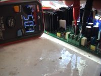
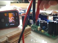
Hi, Stef, ... I have tested for 0,2A and there is something which came out. So, I started this morning at 62V input and set the trimer for 56V output. The dropout voltage when adding the load was big, about 0,5V. However, because the manual said that there should be at least 10V difference between input and output, I made a second test. I set the trimer for 50,1V output and the surprise was that my multimeter cannot measure with two digits at this voltage, but it showed an oscillating value of 50,1V and 50,0V. So I must presume that there is a dropout voltage of 0,05 (half of that missing digit). The conclusion: a) it needs 10V difference between input and output and b) 50 milivolts means 0,1% precision WITHOUT TL431B. Maybe, but this just wishful thinking, maybe if I replace the 15V zenner with the TL431 (and the sorrounding circuit), I might gain more precision.
However, bigger test is needed, such as 5Amps continuously for few seconds (the heatsink will not be enough). In such a case, even if the precision stays the same, the power dissipated on the transistors is huge. P = UI = 10Vds x 5A = 50W per rail, and because there are two mosfets, that would mean 25W on each. They'll get very hot. So, the transformer must offer 100W more for getting 300W instantaneous bass power, which means 400W per mono and 800W per stereo. If I'll go more then stereo ... then I would need two trafos of 800W for quadro. And this is just to catch some miliseconds instantaneous ultra-bass frequency ... same with the 15-19 kHz signals barely audible. I don't know what to say. Maybe we should talk about and see if there is a middle way, not so expensive.
However, bigger test is needed, such as 5Amps continuously for few seconds (the heatsink will not be enough). In such a case, even if the precision stays the same, the power dissipated on the transistors is huge. P = UI = 10Vds x 5A = 50W per rail, and because there are two mosfets, that would mean 25W on each. They'll get very hot. So, the transformer must offer 100W more for getting 300W instantaneous bass power, which means 400W per mono and 800W per stereo. If I'll go more then stereo ... then I would need two trafos of 800W for quadro. And this is just to catch some miliseconds instantaneous ultra-bass frequency ... same with the 15-19 kHz signals barely audible. I don't know what to say. Maybe we should talk about and see if there is a middle way, not so expensive.
Attachments

Hi Moor,
These results do not surprise me. A stabilized power supply, whatever its technicality, has never been a good example of efficiency.
It is not viable to spend all this energy on heat, especially for an improvement in noise that we will only see with a scope.
I don't think you need that much theoretical power. The pulses are so brief (a few milliseconds) that in my opinion the MOSFETs will not even have time to heat up.
This is my humble opinion but others may be more competent on this subject.
Stef.
Hi Stef,
And would be worth trying to use these kits ? Since I already have them (very very cheap from Ali Express) maybe I should design the trafo with several voltages, in order to select either 59Vcc (after rectifier), 65 or 69Vcc (after rectifier).
In my country, the price is not very different for the traf for having more outputs from the same coil. For example, I can design it such as 49-46-42-0-42-46-49 Vac. This way, whatever I'll choose to incorporate the Sigma22 or not, the trafo will offer voltages for all kind of choices. That could be one idea.
It also maybe true that for miliseconds of high power, the mosfets won't heat much.
Another idea might be to choose a 59Vcc fixed voltage for Q17 and hope it won't get into limitation at normal room music listening, even if it drops 6 or 8V during instantaneous high power signals.
But even if that would be the case, the trafo still needs to be designed at minimum 300W per mono, or the drops will be much more due to secondary coil resistence.
I'd like to discuss this further more ... ideas, options, how to do next.
In the meantime I'll continue soldering the remaining 3 motherboards.
Until now, what I can say as conclusions is this:
a) Q17 mini 2.0 tested succesfully at 59Vcc (and 8,2k instead of 7,5 for R25)
b) Sigma 22 tested at 62Vcc input, 56V output, without load ok but 0,5V drop with 0,2Amps load
c) Sigma 22 tested at 62Vcc input, 50,1V output, without load ok and 0,05V drop with 0,17Amps load
Based on these valuable info, found from direct measurements, we can make some plans, ideas, proposals, discussions which worth being conducted here on the forum.
Moor
By the way, I looked at the quad H bipolar chip to replace all these BC546B.
Only two models are available if I didn't make a mistake:
ZHB6792TA bipolar
https://www.mouser.fr/ProductDetail/Diodes-Incorporated/ZHB6792TA?qs=fpoYs8/wAu8RvKxRtSDxMA==
ZXMHC10A07N8TC mosfet
https://www.mouser.fr/ProductDetail/Diodes-Incorporated/ZXMHC10A07N8TC?qs=7E5rbXJDVJo7%2BhNAeCzxNA==
This saves a lot of space on the PCB but it makes the board sensitive because it is single-supplier.
Stef.
Last edited:
From what I read extensively about Sigma 22 the bipolar transistors are best choice, so please choose that one ZHB6792TA bipolar if you wish to create a miniaturised new PCB. Yes, I am motivated to continue testing and making the best outcome having such a superquality Q17 modules.
All characteristics are much better then ordinary BC546, voltages higher, higher amp, higher power ... could be a very good choice. Also the main electrolitics might be chosen miniaturised. The 4700uF or 10.000uF should not be on the board, because they match perfectly in a different location together with the rectifier, and the mosfets should be placed laterally just as they are in original, but much closer to the edges in order to mount them on larger heatsink or even the metal box walls, as I am thinking. Thank you so much Stef for dedicating yourself to this project !
All characteristics are much better then ordinary BC546, voltages higher, higher amp, higher power ... could be a very good choice. Also the main electrolitics might be chosen miniaturised. The 4700uF or 10.000uF should not be on the board, because they match perfectly in a different location together with the rectifier, and the mosfets should be placed laterally just as they are in original, but much closer to the edges in order to mount them on larger heatsink or even the metal box walls, as I am thinking. Thank you so much Stef for dedicating yourself to this project !
I ordered myself a sigma22 PCB to see how it is made. This seems to be an original creation, not just a more or less well-made copy of the AMB one.
https://www.aliexpress.com/item/1005002129896224.html
Stef.
https://www.aliexpress.com/item/1005002129896224.html
Stef.
Attachments
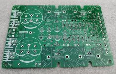
That's the one ! yes, this is what I bought too ! ... great ! except I chose the complete kit with components to solder myself.
I also looked to see if we could put a single large and powerful TO-247 MOSFET in place of two TO-220s. Unfortunately, this requires completely simulating again the design to adapt it to the characteristics of the new MOSFET. Big job.
I also think that for better performance, the power MOSFETs should be matched in pair.
Stef.
I also think that for better performance, the power MOSFETs should be matched in pair.
Stef.
Last edited:
- Home
- Amplifiers
- Solid State
- Q17 - an audiophile approach to perfect sound