

they are smaller because I can't have access to the screws ... so they are 680 uF/63V each. But having in account that there will be a Sigma 22 stabiliser, it won't matter so much ... 2200 uF just did not fit ok for me.
on the other section of the forum someone told me that longer terminals of the Sigma 22 Mosfets might induce oscillations, no matter it is on the DC rail ... I said I am not an expert, but isn't this actually applying for the mosfet terminals of Q17 ? There indeed is high current signal oscillations. The linear DC power supply has constant voltage and variable current on the same polarity, which depends on load.
He said, that because the DC rail is in series with the audio signal, then the length of terminals, dc internal cables, they can induce "absolute audio frequency "modulation"." If that is true, then what kind of internal cables should I use from the rectifier +/- toward the Sigma 22 and then from the +/- output of Sigma 22 toward the Q17 PCB ? ...
unfortunately I can't make them very short because of the distances. My metalic box is half meter long, and at the very back is the transformer, and at the very front is the Quad PCB and a preamp. So the direct current cables are very long already, no matter how long are the mosfet terminals themselves ...
These are exactly the same type of cables I already have inside ... that's ok then ... I don't have to worry much about.
You could try with the prototype.
Lab PSU + 1m wire + sig22 + 1m wire + q17 + speaker
And look with the scope.
Lab PSU + 1m wire + sig22 + 1m wire + q17 + speaker
And look with the scope.
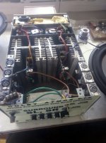
Tested and installed, two more Q17 Mini 2.0 modules. It works great. No audible noise from the Q17 board. I need to change the trafos. They were undersized, and don't give much current. I'll use (as soon as I get it) a SMP800RE configured at +/-63V x 8 Amps (15A peak short). In addition to that I may or may not add the newly developed Sigma 22 for +-55-59V.
Attachments
Great job. I understand why you couldn't put 2200uF. 😉
I hope you won't be disappointed with the switching power supply. I tried with an SMPS600RxE 60V. Ugh. It eats the bass.
Stef.
New mono bridge filter board PCB on the left.
I hope you won't be disappointed with the switching power supply. I tried with an SMPS600RxE 60V. Ugh. It eats the bass.
Stef.
New mono bridge filter board PCB on the left.
Attachments

I was lucky to get the last piece available at 800W ... maybe it will work on my speakers. Because I am listening everything in quadrophonic, I am just guessing that I won't be needing so much bass. SMPS800RE may cover peaks up to 1150W ... I don't know. My trafos are only 300W per stereo so 600W per quadro. But if the SMPS will work ok for a stereo module, then I'll buy another one for the other stereo module. I won't power everything from one single SMPS board. It might not work for bass.
I would still add 10 or 20.000 uF (with some risks) in order to get enough joules for the bass. I'll test if the SMPS800 will accept 20.000 uF or only 10.000.
I would still add 10 or 20.000 uF (with some risks) in order to get enough joules for the bass. I'll test if the SMPS800 will accept 20.000 uF or only 10.000.
Ok, good to know 3800 uF maxim. The worse case scenario, I 'll buy 4 x 800W for each Q17 board separately. I hope it will not be the case. It costs 500$ for 4 SMPS's ... however trafos are not cheaper also. So, not much difference. But boards are small and light, trafos are big and heavy.
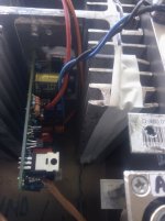
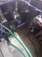
What I feel it might pose a problem is the R11,R12 of 47 Ohms which are heating at 65 degrees Celsius, and they are placed just nearby the C15,C16 heating them at about 45 degrees Celsius. Maybe moving R11,R12 on the back side will solve the problem. The same problem I had with the chinese Quad, and the 560Ohm resistors at 2W and even if I changed to 3W it was still hot, so finally I added them on the back side. On long term function, C15,C16 will shorten their lives ... and/or explode.
It's not the amount of smps supplies, but the possible failure to start if cap bank after it's output is large. Some smps go into protect mode if charging surge from caps is too big. I haven't noticed issues with mean well lrs supplies up to 18k uf (but experiences may differ).
It should depend on the amps they were designed to offer ... and secondly to the caps' ESR. Low ESR maybe worse than ordinary ESR and they still doing the good job.
However, from what I saw on YouTube, there is a guy presenting the inside of a 50.000$ dual mono amplifier. It is made with two 1kW torroidal transformers, two XLR input dual mono power amplifier, 100.000 uF/100V filter, and 8 laterral mosfets per each rail, 4 of total for an stereo XLR input, so 8x4 = 32 mosfets. The metal box is 1 meter wide and 1 meter long, and about 50 kg weight. So, yes, for a huge power peaks, 1kW per mono module is just to have a normal audition of music but with zero clipping, zero distorstions.
I really don't want to think in building such a device. I don't even have enough space in the room. And the costs are just prohibitive.
But its was very nice to watch the videoclip on YouTube.
I know it's not good to refer to physics in such a forum. Nevertheless, I do it anyway:
The source impedance of the power supply is the limiting factor for the power that an amplifier like the Q17, which has a very low internal resistance, can deliver at the speaker output. Therefore, while it's theoretically possible for an 800W switching power supply to have a similar internal resistance as a 50VA toroidal transformer in the tone-frequency range, I don't understand the purpose of using the switching power supply.
Furthermore, filtering out the 50 Hz hum of the power supply is much simpler and requires less effort than filtering the noise from a switching power supply.
But everyone must decide for themselves how many obstacles they want to put in their own way.
Its absolutely OK to refer to physics in such a forum!]
The purpose of a SMPS is to reduce size and weight and perhaps losses too. Some SMPS do power-factor correction too which may be important in some situations.
The purpose of a SMPS is to reduce size and weight and perhaps losses too. Some SMPS do power-factor correction too which may be important in some situations.
Here they tested a 100W power amplifier, having a SMPS300RE supply and the graphs are looking good. An indirect conclusion of this is that the SMPS did not alter the signal, neither added noises. https://www.audiosciencereview.com/...ics-sylph-d200-amplifier-module-review.25295/
- Home
- Amplifiers
- Solid State
- Q17 - an audiophile approach to perfect sound