Trying to understand the subtle features of Quad operation. So, this emphasis in the low frequency response is a design choice or is it an essential feature of this circuit architecture?
I really appreciate your investigation into Quad's behaviour at the low end. I also noticed that the top end is not flat. Can you pls explain how the top end gets influenced?
I think this cap will not 'harm'. You can always remove it! For bipolar op-amp, it may be 'essential'.
Is not needed. If still want to have one at the opamp input, go for 100pF silver-mica.
Regards,
Tibi
This is optional, if there is an instability because of oscillation, we could consider this just in case!
Such snubbers are hard to calculate and the zener will hurt already a lot.
Zener parasitic capacitance is not negligible at all (200pF - 300pF)
Regards,
Tibi
Did you try something like this to tame the oscillations?
Not a good idea. Negative feedback resistor 560ohm is part of current dumping bridge. Do not touch current dumping bridge unless you change or adjust something for better.
Regards,
Tibi
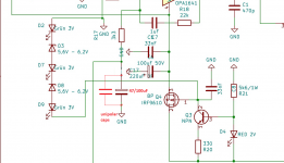
In case of what? I find gate protection zeners very audible and not in a good way.
Once all the unnecessary protections are added, not forgetting output relays and fuses everywhere, the sound may become quite sad.
Fully agree with you. Zener's have big parasitic capacitance.
People like to over-engineer things, sometimes for good, sometimes for bad.
In this case adding gate-source Zener will protect output only if Q5 or Q6 will fail. If I would include these in my own amplifer ? A big NO.
Regards,
Tibi
I really appreciate your investigation into Quad's behaviour at the low end. I also noticed that the top end is not flat. Can you pls explain how the top end gets influenced?
Remove the extra parts, added by Tim, and the top will become flat. 🙂
As far I remember , in my simulations, 680nF in place of C7 will flat lower end graph. I prefer 1uF because I use exotic caps and 1uF is available.
Regards,
Tibi
Hello Tibi,
it may seem to you that we ruin your circuit, but actually we all just want to play. The nice thing is, you can solder nonsense, listen to it and desolder it again.
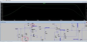
Now to the topic of high frequency filtering. For this I extend the simulation up to 10MHz, this is basically nonsense, but shows how the filters should behave in theory. In addition the hint: if I use capacitors in the high frequency range the quality must be correct, otherwise the capacitor does not work.
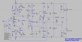
First the output simulation with the filters of the original.
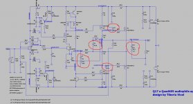
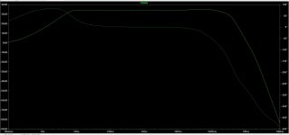
Then a modification from me, with the aim to reduce L and to optimize the filter a bit. Clear statement: I have no idea how this sounds.
Also to note is that I still can't simulate the OPA1611 in a stable way. This oscillates.
Now to the theory:
In the high tone there are limits, depending on the reaction time of the OP. This leads without filter to about -50 dB at 10MHz (theory!).
The output filter reduces the susceptibility to produce oscillation and harmonics. Therefore these filters must be designed in such a way that they work above 100 kHz if possible and are fully effective there.
The aim of an amplifier is therefore to ensure that it does not produce any nonsense - to be precise, unacceptable reverberation - and this is best achieved by heavily attenuating the frequency range well above the audio range. Now it is important that in the audio range the phase turns only minimally, so that speakers that have a high-quality passive crossover also play cleanly on it.
Also note that any capacitor in the circuit will not work ideally. The capacitors, which are so small that they only become effective above 100kHz, are also very important here. If they have too high a tan δ, then the filter will not work as simulated, but will be much flatter. This is very easy to measure. The next point is that if the capacitors are too large, these blur the pulse mapping, there is currently a very extensive thread here in the forum. C7 must work in the tonal range, so its quality sound is crucial. Forming C7 in MKP10+FKP1 will never come close to the sound of a tin foil, only I also realize that not everyone here in the forum wants to spend 20$ for a capacitor. So for me the alternative with Wima is the cost compromise. But, I have to add, if you have speakers, such as Dali Epicon, that contain very well engineered but particularly cheap crossovers, a C7 in tin foil is also unnecessary. I now have to match everything in my sound chain. This is surprising when you realize that Dali is giving away a lot of the potential of its drivers because they are now two classes lower than necessary in cavity damping and crossover components.
The next issue in the quality of play of analog audio is Q-factor. This is a very difficult subject. A quality of less than 0.5 can be measured very well and simulated very well, but this also sounds dusty, dead....
A Q of 0.5 would be ideal in theory, except we don't have ideal components. Therefore, a Q of 0.55 sounds close to the physical ideal with very good component quality. This means that an analog circuit should always have a tendency to oscillate, but never too much. That is the art.
Tibi, I'm just thinking of it that way because I derive that from crossover design of loudspeakers. You are welcome to add to it.
it may seem to you that we ruin your circuit, but actually we all just want to play. The nice thing is, you can solder nonsense, listen to it and desolder it again.
Now to the topic of high frequency filtering. For this I extend the simulation up to 10MHz, this is basically nonsense, but shows how the filters should behave in theory. In addition the hint: if I use capacitors in the high frequency range the quality must be correct, otherwise the capacitor does not work.
First the output simulation with the filters of the original.
Then a modification from me, with the aim to reduce L and to optimize the filter a bit. Clear statement: I have no idea how this sounds.
Also to note is that I still can't simulate the OPA1611 in a stable way. This oscillates.
Now to the theory:
In the high tone there are limits, depending on the reaction time of the OP. This leads without filter to about -50 dB at 10MHz (theory!).
The output filter reduces the susceptibility to produce oscillation and harmonics. Therefore these filters must be designed in such a way that they work above 100 kHz if possible and are fully effective there.
The aim of an amplifier is therefore to ensure that it does not produce any nonsense - to be precise, unacceptable reverberation - and this is best achieved by heavily attenuating the frequency range well above the audio range. Now it is important that in the audio range the phase turns only minimally, so that speakers that have a high-quality passive crossover also play cleanly on it.
Also note that any capacitor in the circuit will not work ideally. The capacitors, which are so small that they only become effective above 100kHz, are also very important here. If they have too high a tan δ, then the filter will not work as simulated, but will be much flatter. This is very easy to measure. The next point is that if the capacitors are too large, these blur the pulse mapping, there is currently a very extensive thread here in the forum. C7 must work in the tonal range, so its quality sound is crucial. Forming C7 in MKP10+FKP1 will never come close to the sound of a tin foil, only I also realize that not everyone here in the forum wants to spend 20$ for a capacitor. So for me the alternative with Wima is the cost compromise. But, I have to add, if you have speakers, such as Dali Epicon, that contain very well engineered but particularly cheap crossovers, a C7 in tin foil is also unnecessary. I now have to match everything in my sound chain. This is surprising when you realize that Dali is giving away a lot of the potential of its drivers because they are now two classes lower than necessary in cavity damping and crossover components.
The next issue in the quality of play of analog audio is Q-factor. This is a very difficult subject. A quality of less than 0.5 can be measured very well and simulated very well, but this also sounds dusty, dead....
A Q of 0.5 would be ideal in theory, except we don't have ideal components. Therefore, a Q of 0.55 sounds close to the physical ideal with very good component quality. This means that an analog circuit should always have a tendency to oscillate, but never too much. That is the art.
Tibi, I'm just thinking of it that way because I derive that from crossover design of loudspeakers. You are welcome to add to it.
Attachments

Hello Tim,
Crazy things may lead to great discoveries. 🙂
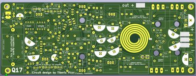
Anyone is very welcome to play with this circuit. In fact I'm very curious what other people will try and how this can be improved.
Regards,
Tibi
Crazy things may lead to great discoveries. 🙂
Anyone is very welcome to play with this circuit. In fact I'm very curious what other people will try and how this can be improved.
Regards,
Tibi
one more thing: for a speaker impedance of 4ohms, an R31 with 3.3 ohms is pretty ideal. Then the C17 with 100nF is also suitable. The simulation example above refers to a load with 8 ohms.
Hello Tibi,
it may seem to you that we ruin your circuit, but actually we all just want to play. The nice thing is, you can solder nonsense, listen to it and desolder it again.
Now to the topic of high frequency filtering. For this I extend the simulation up to 10MHz, this is basically nonsense, but shows how the filters should behave in theory. In addition the hint: if I use capacitors in the high frequency range the quality must be correct, otherwise the capacitor does not work.
First the output simulation with the filters of the original.
Then a modification from me, with the aim to reduce L and to optimize the filter a bit. Clear statement: I have no idea how this sounds.
Also to note is that I still can't simulate the OPA1611 in a stable way. This oscillates.
Now to the theory:
In the high tone there are limits, depending on the reaction time of the OP. This leads without filter to about -50 dB at 10MHz (theory!).
The output filter reduces the susceptibility to produce oscillation and harmonics. Therefore these filters must be designed in such a way that they work above 100 kHz if possible and are fully effective there.
The aim of an amplifier is therefore to ensure that it does not produce any nonsense - to be precise, unacceptable reverberation - and this is best achieved by heavily attenuating the frequency range well above the audio range. Now it is important that in the audio range the phase turns only minimally, so that speakers that have a high-quality passive crossover also play cleanly on it.
Also note that any capacitor in the circuit will not work ideally. The capacitors, which are so small that they only become effective above 100kHz, are also very important here. If they have too high a tan δ, then the filter will not work as simulated, but will be much flatter. This is very easy to measure. The next point is that if the capacitors are too large, these blur the pulse mapping, there is currently a very extensive thread here in the forum. C7 must work in the tonal range, so its quality sound is crucial. Forming C7 in MKP10+FKP1 will never come close to the sound of a tin foil, only I also realize that not everyone here in the forum wants to spend 20$ for a capacitor. So for me the alternative with Wima is the cost compromise. But, I have to add, if you have speakers, such as Dali Epicon, that contain very well engineered but particularly cheap crossovers, a C7 in tin foil is also unnecessary. I now have to match everything in my sound chain. This is surprising when you realize that Dali is giving away a lot of the potential of its drivers because they are now two classes lower than necessary in cavity damping and crossover components.
The next issue in the quality of play of analog audio is Q-factor. This is a very difficult subject. A quality of less than 0.5 can be measured very well and simulated very well, but this also sounds dusty, dead....
A Q of 0.5 would be ideal in theory, except we don't have ideal components. Therefore, a Q of 0.55 sounds close to the physical ideal with very good component quality. This means that an analog circuit should always have a tendency to oscillate, but never too much. That is the art.
Tibi, I'm just thinking of it that way because I derive that from crossover design of loudspeakers. You are welcome to add to it.
Great analysis! Can we practically make a 0.2uH coil for the bridge? or it will form part of an inductive resistor?
Since the coil is partially unpainted, it is very easy to bridge the turns. So you can use the inner windings and bridge the outer ones. It is tedious and unnecessary to determine now exactly whether you bridge the outer two or three turns on both sides.


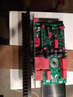
Hi Tim, I was wondering if something like this would fit the bill in quality and pcb real state?
Hello Atiq,
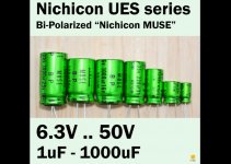
the parallel circuit of C2 does not sound good. I have all kinds of electrolytic capacitors there now and I also bought the MUSE. A single Muse sounds good - just like Tibi has - two 220uF/25V in series sound better. So I have touched the layout again and enlarged the footprints.
At the input there are now Rin+ and Rin-. It's up to you to decide whether you want to solder wire or resistors. I want to experiment with it to test whether a resistor between GND and input (-) has an effect and what effect.
Regards Tim
Attachments
I only have one pair of output transistors in my current setup. A setup like Alex's is well suited for pushing a car's subwoofers, but if you want to generate real volume, you should then operate two such power amplifiers each in bridge mode - i.e. balanced - so that with four boards you also set up an amplifier with several hundred watts of power, right?
My previous setup with double output transistors is so powerful in the bass that really few speakers need it, three pairs of outputs even less...
My previous setup with double output transistors is so powerful in the bass that really few speakers need it, three pairs of outputs even less...
- Home
- Amplifiers
- Solid State
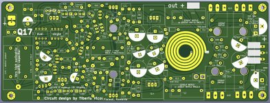
- Q17 - an audiophile approach to perfect sound