Tim,
I'm sending the Gerber to JLCpcb. Any further refinement are you planning on the current pcb revision?
Thx
not now, I'll wait for the delivery from JLC first and build it up. But I do not think that I can still optimize relevant there.
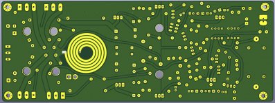
With the board with the two sockets, it is really difficult to decide which is more suitable.
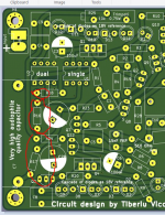
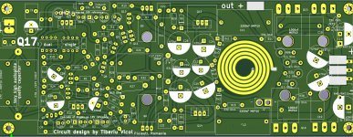
The first one has space on the side of the OP slots, the second one is missing them, but you can reach the slots from the front. Both are not ideal, but to change this is really complex.

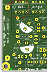
No, I need for C7 a cab like Audy kpsn for my sound experience. It has a diameter of 20 mm and is very large for 1uF.
There is also tin foil from mundorf available and there is certainly something equivalent from clarycap for a lot of money.
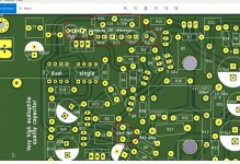
Look at the picture of my prototype, there you can also see the C7
Regards Tim
There is also tin foil from mundorf available and there is certainly something equivalent from clarycap for a lot of money.
Look at the picture of my prototype, there you can also see the C7
Regards Tim
Last edited:
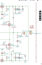
Yes, of course. I use a faster OPA than Tibi, this OPA cannot be simulated because it oscillates. In Tibi's original circuit it also oscillates - sounds like a tin can - so I added more filters. Tibi also does not have the many capacitors in his amplifier. Therefore I have labeled all added components.
Attached are KiCad files, no idea if you can handle them.
Attached are KiCad files, no idea if you can handle them.
Attachments
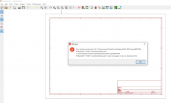
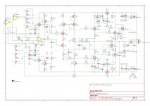
Can you simply attach the schematic png file? KiCad file doesn't work for me.
Attachments
No, I did like a sheep what Tibi told me to do. 😀
One piece sounds great more sound also not bad.
Therefore, I have two paired to a delta of +- 2mV Vgs and installed without source resistor. It sounds like a very full grown amp, not like the monobocks you can buy in the expensive stores.
One piece sounds great more sound also not bad.
Therefore, I have two paired to a delta of +- 2mV Vgs and installed without source resistor. It sounds like a very full grown amp, not like the monobocks you can buy in the expensive stores.
I'll tell you how it sounds with Muses01😀
First, I need to get my pcb from JLC.
I don't think I'll need the R-C, C27/R22, as I don't plan to use any ultra fast op-amps.I'll add a 220pf cap across R16 though.
First, I need to get my pcb from JLC.
I don't think I'll need the R-C, C27/R22, as I don't plan to use any ultra fast op-amps.I'll add a 220pf cap across R16 though.
Why not with input capacitor.
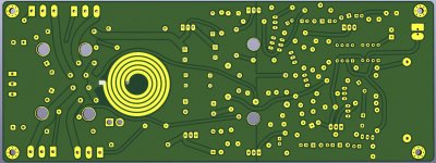
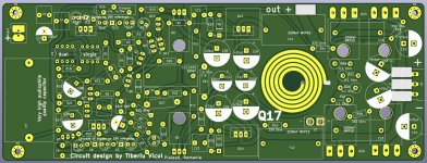
I still had the idea to split the C7 into two capacitors, which are already used on the board. The duo should also be able to play good performace.
And I still have space in the back for electrolytic capacitors with pitch 7.5 mm and 18 mm diameter.
I still had the idea to split the C7 into two capacitors, which are already used on the board. The duo should also be able to play good performace.
And I still have space in the back for electrolytic capacitors with pitch 7.5 mm and 18 mm diameter.
Attachments

It's fun to equip the board for all eventualities....
What should be the resistor and capacitor that you have entered at the output transistor?
What should be the resistor and capacitor that you have entered at the output transistor?
Did anyone simulate the loop gain of this thing? The stability is questionable.
Ltspice asc file is included in project, so anyone may simulate.
Your comments/recommendations are welcome.
Regards,
Tibi
Why not with input capacitor.
There is no need for one on a jfet input, but some input protection can be added, even many opamps have already.
In case for bipolar input, you may add a capacitor. 100nF to 330nF. However, this will add his own sound coloration. Not for me.
Regards,
Tibi
Last edited by a moderator:
- Home
- Amplifiers
- Solid State
- Q17 - an audiophile approach to perfect sound