Guy's how hot does this amp run ? I have plenty of BIG finned heatsinks, but I have these as well. 180 x 85x90. Should be sufficient with a slow turning fan.
The amp will run cold at low levels and warm at high level. You do not need forced ventilation.
Regards,
Tibi
Thank you for your feedback and contribution, Tim.
As now you know the sound of the amplifier, I suggest you to try synchronous rectification. I have posted here source and gerbers for a THT version Ideal bridge rectifier GB
Regards,
Tibi
Hello Tibi,
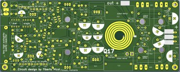
I have not used active rectifiers yet, but it is interesting. The rectifier made of CSD19503KCS and LT4320IN8-1#PBF is a very simple circuit for frequencies up to 600 Hz, it is written in the data sheet. My experiments with headphone amplifiers have shown a correlation between the sound and the distortions of the transformer. With the Q17, I can now detect neither a power hum nor any sound colouration.
For me, it would now be primarily understandable that I achieve a lower power loss and a higher DC voltage. In terms of sound, I can't imagine what the advantage of active rectification is.
I have also compared rectifiers made of the new SiO diodes with particularly low reverse current with the cheapest bridge rectifier, without any audible difference...
Your active rectifier that works up to 400 kHz is in a different league, as it should now be able to control the harmonics of the power supply. But I ask myself, what use is that if the essential factor is the smoothing by capacitors? When I compare my power supply experiments, the amount of MKP + FKP in the current filtering is much more relevant than the rectifiers, that's my current state of knowledge, enlighten me about things I don't know yet, I still have to learn. 😉
Regards Tim
Tim, I need a pair of pcbs for testing.Happy to share the cost. Do u have a spare or could you share your latest Gerber? A
no problem, the last ones are already ordered. I ordered 10 of them at once, as they are much less work to assemble. I don't think you want the old layouts.
If you want to buy boards from me, it would actually make sense for me to order the output transistors from Mouser for you at the same time, so that I can also send you the paired ones. Do you want to build the AMP with the OPA1611?
If you want to buy boards from me, it would actually make sense for me to order the output transistors from Mouser for you at the same time, so that I can also send you the paired ones. Do you want to build the AMP with the OPA1611?
Attachments
I have created a list of Reichelt components, so it should be easier to order the components. This component list is for the assembly of the new board. There are two 8.2k resistors in it, that is R23 and R24. I think these values are ideal. I use the 33nF FKP2 instead of the 100nF MKS - I think I already mentioned that.
Security Check
The following components are missing:
FQP3P20
FQP3N30
FQA46N15
FQA36P15
OPA1611
Maybe Muse capacitors, 1x 100 uF each (like Tibi uses) or 2x 220 uF, I will test this out.
The following components would be possible for the power supply:
Inexpensive transformer from Reichelt: RKT 30030
There is an active rectifier from Mouser - you will need two of these:
2x LT4320IN8-1#PBF
8x CSD19503KCS
2x 100nF
2x (or more) ALC10S1103DH
Regards Tim
Tim,
I'd test with Muses-01 and other regular op-amps. I don't plan to use smd parts though.
Is it possible to use dual op-amps in the DIP8 socket in your pcb?
Thanks
I'd test with Muses-01 and other regular op-amps. I don't plan to use smd parts though.
Is it possible to use dual op-amps in the DIP8 socket in your pcb?
Thanks
HTML:
Is it possible to use dual op-amps in the DIP8 socket in your pcb?The pin assignment of single and double amplifiers are different.
Tim,
I'd test with Muses-01 and other regular op-amps. I don't plan to use smd parts though.
Is it possible to use dual op-amps in the DIP8 socket in your pcb?
Thanks
You' re really funny, I only just now noticed that the Muse01 are from JRC, I always threw away the OP of those as they play really stubby and dead. I wouldn't set up the amp with them, even if it works well with them.
We all are different, aren't we! Muses01 exceeded my expectations in sound signature in a pre-amp application. Got few of those left over, not cheap though. No harm testing those in Q17. We shall see how it goes.
Got plenty of other regular op-amps available as well. If the current pcb doesn't allow op-amp rolling, it should be considered as a room for future improvements.
Got plenty of other regular op-amps available as well. If the current pcb doesn't allow op-amp rolling, it should be considered as a room for future improvements.
Yes, that's true, we listen differently and we also have very different speakers, players...
For those who still have no idea how to get an OPA1611 or OPA1641 socketed, I recommend..:
Peter Soki
Martos Flóra u. 21
Dédestapolcsány
3643
Ebay name: sokhu26
I have bought many socketed operational amplifiers from him. He buys the components in Texas, and soldering is very good.
He only sells his work on Ebay and sends reliably and quickly.
We all are different, aren't we! Muses01 exceeded my expectations in sound signature in a pre-amp application. Got few of those left over, not cheap though. No harm testing those in Q17. We shall see how it goes.
Got plenty of other regular op-amps available as well. If the current pcb doesn't allow op-amp rolling, it should be considered as a room for future improvements.
The space doesn't get any more on the board, but that's how it should go. I have connected the inputs of the unused OP to GND so that it doesn't do anything nonsense.
Attachments
I have created a list of Reichelt components, so it should be easier to order the components. This component list is for the assembly of the new board. There are two 8.2k resistors in it, that is R23 and R24. I think these values are ideal. I use the 33nF FKP2 instead of the 100nF MKS - I think I already mentioned that.
Security Check
The following components are missing:
FQP3P20
FQP3N30
FQA46N15
FQA36P15
OPA1611
Maybe Muse capacitors, 1x 100 uF each (like Tibi uses) or 2x 220 uF, I will test this out.
The following components would be possible for the power supply:
Inexpensive transformer from Reichelt: RKT 30030
There is an active rectifier from Mouser - you will need two of these:
2x LT4320IN8-1#PBF
8x CSD19503KCS
2x 100nF
2x (or more) ALC10S1103DH
Regards Tim
Hi Tim,
I'm making a BoM for the pcb. Where do you install these parts?
2x LT4320IN8-1#PBF
8x CSD19503KCS
2x 100nF
2x (or more) ALC10S1103DH
On the power supply board?
Thx
Yes, I have changed the size of the two resistors.
The amplifier sounds a bit more "real" with the 8.2k in the DC servo.
R24 in 8,2k with the 10k potentiometer allows a control range from 8,2k to 18,2k so you can adjust the driver stage of the amplifier to the supply voltage from about +-33V to +-55V.
I have drawn another PCB (not as nice and compact as Tibi) for the active rectifier with the space for the cheap cooler - although this should actually be unnecessary.
Reichelt: 576802B00000G
I find the cooler super practical, as it works very well with a small load.
Attachments
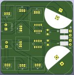
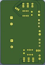
I suggest you to rearrange LT4320 in that way that traces from chip to mosfet gates to be shorter.
Move C1 and C2 as close as possible to LT4320.
Mosfet's do not need heatsink, therefore use the space for capacitors or anything else.
Regards,
Tibi
Move C1 and C2 as close as possible to LT4320.
Mosfet's do not need heatsink, therefore use the space for capacitors or anything else.
Regards,
Tibi
Last edited by a moderator:
For original DIP-8 OP this variant is easier to change the ICs. The connection of the C7 is no longer in the way.
I do not sell this board.
Tim,
I'm sending the Gerber to JLCpcb. Any further refinement are you planning on the current pcb revision?
Thx
I suggest you to rearrange LT4320 in that way that traces from chip to mosfet gates to be shorter.
Move C1 and C2 as close as possible to LT4320.
Mosfet's do not need heatsink, therefore use the space for capacitors or anything else.
Regards,
Tibi
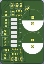
i think that's how it's useful. I also attached the GND for the speaker outputs and the solder pads for the many cables for those who like me do not want to screw.
Attachments
- Home
- Amplifiers
- Solid State
- Q17 - an audiophile approach to perfect sound