Good work.
Did u consider protection diodes?
Thx
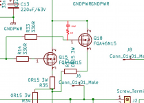
Mosfets have already such substrate diode and is fast enough.
On other hand, a gate to source zener may be added, just in case ...
Regards,
Tibi
Hello Tibi,
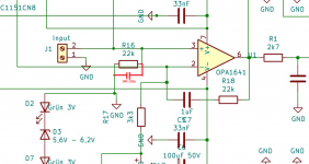
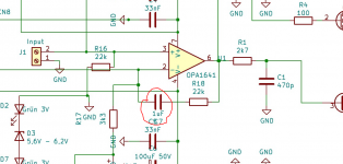
"C in" this is not an input capacitor but one against GND, parallel to R16. The size 220pF can be advantageous depending on the signal source.
An input capacitor like you mean is really a shame with this amplifier. We don't want to kill the signal that much now. A few diodes here and there, which usually block and thus will do nothing, should not damage the circuit.
Hello Vrystaat,
I added a gate protection, you can build it with Z diodes Z1 to Z4.
Attachments
This is optional, if there is an instability because of oscillation, we could consider this just in case!
I disagree with you that this is a convenient place to equalize the amplifier. The filter parallel to R6 is much more efficient. I must mention that with your filter you need it 4x, mine 1x.....
The simulation says -8dB at 1MHz. Is that supposed to help?
Last edited:
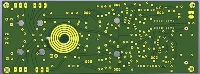
These are optional, will not need in every case, aimed at high frequency oscillations. We can only know their requirements by looking at the scope. Your pcb layout is neat, may not need them at all! Thanks for the RFI cap and protection diodes!!
I have a problem attaching images now,
Plse google mosfet gate protection. A 1N4148 with a zener is used, and polarities differ with the N and P fets.😉
Regards
Plse google mosfet gate protection. A 1N4148 with a zener is used, and polarities differ with the N and P fets.😉
Regards
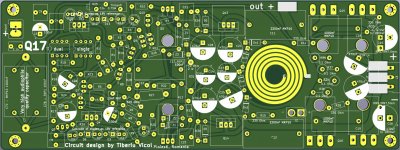
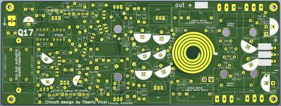
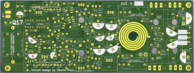
I love the angular placement of the components. Thats what happens when you aim for the truly optimal layout!
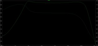
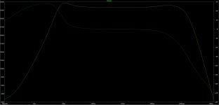
I have considered and simulated how to prevent the output from oscillating even "better".
With 10nF from drain to power I get an effective result. 33nF is too much, that gives a corner in the frequency response.
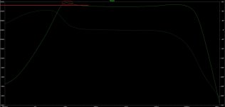
At first the diagram of the simulation of my setup, then with the two additional capacitors C Q5+ and C Q6+.
With 10nF from drain to power I get an effective result. 33nF is too much, that gives a corner in the frequency response.
At first the diagram of the simulation of my setup, then with the two additional capacitors C Q5+ and C Q6+.
Attachments

I have a problem attaching images now,
Plse google mosfet gate protection. A 1N4148 with a zener is used, and polarities differ with the N and P fets.😉
Regards
It is easier to use only Z-diodes for overvoltage protection. Of course, you can also use a combination of normal diode and Z-diode, then it is relevant that you connect them correctly oriented in series.
The simulation says:
It's not a good idea.
Reason:
The phase is rotated more.
This capacitor already behaves unfavorably at 10kHz.
It's not a good idea.
Reason:
The phase is rotated more.
This capacitor already behaves unfavorably at 10kHz.
On other hand, a gate to source zener may be added, just in case ...
In case of what? I find gate protection zeners very audible and not in a good way.
Once all the unnecessary protections are added, not forgetting output relays and fuses everywhere, the sound may become quite sad.
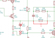
the R-C, C27/R22 corrects a little the phase in the high frequency range.
I did this because I wanted to replace the 2nd order output filter from L1/C17/R31.
Both filters together complement each other well. Therefore I use both of them.
I did this because I wanted to replace the 2nd order output filter from L1/C17/R31.
Both filters together complement each other well. Therefore I use both of them.
In case of what? I find gate protection zeners very audible and not in a good way.
Once all the unnecessary protections are added, not forgetting output relays and fuses everywhere, the sound may become quite sad.
Fortunately, this is not a ready-made amplifier. But since everyone has their own priorities, the board is well equipped with almost everything there is, even if no one will ever build it that way.
the R-C, C27/R22 corrects a little the phase in the high frequency range.
I did this because I wanted to replace the 2nd order output filter from L1/C17/R31.
Both filters together complement each other well. Therefore I use both of them.
C27R22 compensates for 21.2kHz pole. What happens if you raise the pole to, say, 48kHz (15nF+220r)?
At 220 Ohm / 15nF the change is small. In the region of 60kHz there is an overshoot which increases with decreasing resistance.
Interestingly, with 220 ohms / 15nF and the two 10nF at Q5 and Q6, the phase at 10kHz has rotated only 2° and the level maxima is at 75kHz. Here there seems to be a favorable mutual influence. This worsens with lower resistance, just as with higher. With lower capacity it does not work either.
Interestingly, with 220 ohms / 15nF and the two 10nF at Q5 and Q6, the phase at 10kHz has rotated only 2° and the level maxima is at 75kHz. Here there seems to be a favorable mutual influence. This worsens with lower resistance, just as with higher. With lower capacity it does not work either.
No, you have not understood the circuit at all.
If C7 was a wire, then the OP would be wired as usual and operate normally. But as the OP should work as a DC servo, C7 is responsible for the frequency spectrum above 10Hz. Below 10Hz C2 is important. C2 and C7 produce an emphasis in the frequency response at approx. 10Hz, this is minimal, but shows their dependence on each other.
For this reason it is important that C7 works ideally in the frequency range 10Hz to 100kHz with very little loss/error.
C2 must work cleanly in the frequency range up to 10Hz, above that it must have some attenuation. I have not tried whether this correlates with R32, as the change in R32 affects noise from the power system. So a very high loss pair C2 of two 220uF is a good compromise.
- Home
- Amplifiers
- Solid State
- Q17 - an audiophile approach to perfect sound