Hello Atiq,
the parallel circuit of C2 does not sound good. I have all kinds of electrolytic capacitors there now and I also bought the MUSE. A single Muse sounds good - just like Tibi has - two 220uF/25V in series sound better. So I have touched the layout again and enlarged the footprints.
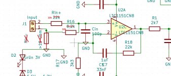
At the input there are now Rin+ and Rin-. It's up to you to decide whether you want to solder wire or resistors. I want to experiment with it to test whether a resistor between GND and input (-) has an effect and what effect.
Regards Tim
I tested the resistors at the input: a voltage splitter 1:1 (R16 = 10k and Rin+ = 10k) is pretty ideal for me, because then the control range of the potentiometer reaches from quiet to ultra loud. A resistor between the (-) input and GND only produces hum, I was afraid of that, but I wanted to try it out. So I installed a wire for Rin-.
I have now installed a Q17 in a small aluminium housing.
I nearly despaired, but now it works.
The first thing that is not clear to me is that I have swapped the Q13s in both power amplifiers. one did not start. the other very slowly. The component tester claims that the cut IRF610s are OK. My question, is it possible that R29 is perhaps chosen a little high? Would 6k8 perhaps be more suitable?
Then I had one touch point on Q5 with the radiator, R10 was smoking, so I could identify this fault too.
Now it plays very nicely.
It is one with only one pair of output transistors. I would prefer this for nice music listening. The Q17 with output pairs selected in pairs was a touch more massive, more merciless at high levels. This new one is a shade more sensitive, the right choice for me.
Tibi's concept of divided mass obviously works very well. I haven't used an amplifier without a power filter for a long time. This one has an ordinary toroidal transformer. With many amplifiers you can hear the harmonics of the transformer. I am very impressed with the circuit.
I tested the resistors at the input: a voltage splitter 1:1 (R16 = 10k and Rin+ = 10k) is pretty ideal for me, because then the control range of the potentiometer reaches from quiet to ultra loud. A resistor between the (-) input and GND only produces hum, I was afraid of that, but I wanted to try it out. So I installed a wire for Rin-.
This is your current input arrangement, right?
Attachments
Hello Tibi,
once again, huge compliments.
I now have the amp running at home and it sounds fantastic. Compared to that, my old amp sounds downright fuzzy. The bass foundation is also impressive. The treble seems endless and the naturalness - I don't have the words to describe it.
I have never heard such an acoustic stage, not even with open buffle speakers.
Regards Tim
how did you end up with the compensation scheme?
I don't understand.
Do you think which filters I have installed?
I have 499 ohms + 15nF, and in the output 13 turns of 1mm air core coil, 4.7 ohms and 100nF.
The printed coil sounds too soft to me.
Last edited:
fredlock, it is a good question. Already addressed, but I'll try to add some more info.
Q17 in running mainly in class B with negligible AB operation. There is no need for bias adjustment, unless you use lateral mosfet or some other vertical mosfet with different Vgs threshold.
In case of Exicon laterals R11 and R12 = 10ohm.
Q12 & Q6 form a ccs. If you still want to slightly adjust bias, this can be achieved by changing ccs current trough R13. A series 22ohm multiturn potentiometer + 5ohm resistor may replace R13. This way you can adjust current trough class A stage, formed with Q5 and Q6. Together with ccs current the bias voltage over R11 and R12 will have a variation, changing final stage operation. For symmetry, R10 must mach pot+5ohm.
Please also note, if you want thermal tracking, Q12 need to be mounted on heatsink. Q12 Vbe is the main ccs voltage reference.
DC offset is achieved trough servo with R23+R17+C2.
More details at Q17-a-QUAD405-audiophile-approach/Q17.pdf at main * tvicol/Q17-a-QUAD405-audiophile-approach * GitHub
Regards,
Tibi
Thank you Tvicol for the detailed explanation. Really appreciate it. I'm interested to build the amp.
Hello Tibi,
once again, huge compliments.
I now have the amp running at home and it sounds fantastic. Compared to that, my old amp sounds downright fuzzy. The bass foundation is also impressive. The treble seems endless and the naturalness - I don't have the words to describe it.
I have never heard such an acoustic stage, not even with open buffle speakers.
Regards Tim
This make me very happy ! 😀
Regards,
Tibi
Hi Alex and Tim. Are you selling boards?
no.
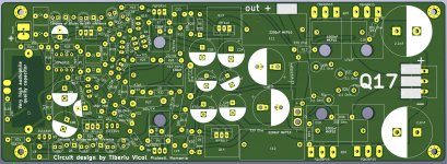
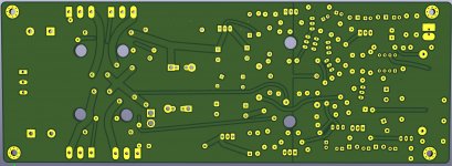
i have uploaded an experiment board here that has some not needed footprints on it.
The unlabeled diodes are for scaredy-cats, I don't understand their sense, because they also burn out in case of defects.
Only one operational amplifier may be installed.
The capacitors C-Q5 and C-Q6 I have not used so far, I would currently leave them empty.
It is up to you whether you equip the output single or double with source resistor. I have built it without source resistor with only one pair of transistors.
R24 = 8k2
R23 = 8k2
Rin- = wire
Rin+ = 10k
R16 = 10k
Cin = empty (my audio cable has enough capacity)
Q9 = ZVP2106A
Q11 = ZVP2106A
Q8 = ZVN4206A
R25 = 0 for + - 33V
R25 = 9k for + - 50V
or something between
I have made a list of components on Reichelt.de. This is incomplete, because the four QFET, an OPA1611 socketed, C7 and the two Muse 220/25V are missing.
Last edited:
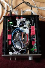
Pictures of the finished amplifier.
Not nice inside, there is very little space in the case. The PCB for the active rectifiers are not there yet, so 4 MUR diodes have to rectify the current.
The amplifier has a 2x 24V transformer, which produces 2x 35V DC.
This certainly does not meet the expectation in terms of sound, so I recommend everyone to use a larger enclosure if you do not have experience in how to minimize and also detect mutual induction.
Attachments

Guy's.
Will the 3 pair bord of Alex be OK with +-66VDC rails ?
FQA46N15/FQA36P15 transistors are rated at 150V. This limit absolute maximum voltage operation at +/-75V. This is pure theoretic, because in practice will never run fully saturated that one transistor to be exposed to full rail voltage. However, you must know that even at +/-66V transistors will run very easy out of SOA (Safe Operating Area).
+/-60V would be more appropriate.
Also, take care on capacitors voltage rating.
If you want to go for higher rail voltages, IXYS or Exicon may be a solution.
Regards,
Tibi
Thank you Tibi,
I will take some windings off the toroidal, will not be a problem, it is a 600VA jobbie.
I will take some windings off the toroidal, will not be a problem, it is a 600VA jobbie.
- Home
- Amplifiers
- Solid State
- Q17 - an audiophile approach to perfect sound