well great! we need to make more Pumpkins!! ZenMod will be soooo sad..
Wait! I have another question: does an F4 used single ended and one used balanced have the same gain? I guess so...?.........
Wait! I have another question: does an F4 used single ended and one used balanced have the same gain? I guess so...?.........
mpmarino said:
Yes but you'd then have a amp that would strain to run a 8r load ...No?
I don't think it's a strain--not if the driver is a 110db 1w1m horn. I get 2 amps total bias, not 6 (which is what the midbass units will have per pcb). The overall wattage output is down, but that's what I want.
jeeeeeeeeeeeez!!
god mornin' to all, you are all drekin' nutz!!
seems that nobody in fact read all these crazy threads ...
it will be hard to cover all issues from last posts ......
woodie :
go to page one or two of F4 thread and look my mini F4 variant - for 16 ohms ; crank bias to 1A and you'll be good for at least 8W/8E in A class
like you said
CY :
why should I ? for unbal conversion ? use XLR with shorted 1 and 3 ......
if you mean - switching just ground on used input ( all inputs always connected to signal rails) ........ I'm not so hysteric regarding little takamisawa relays in signal path ....... this is no Blowtorch ,and never will be
greedy danske :
yes - it's intended to use 4 channel attenuator ; not exactly twice teuerer than simple stereo but certainly better and more versatile .
on input where 1 and 3 are shorted in XLR source's cable , lower leg of attenuator is shorted automatically , so you have plain stereo 2 channel pot automatically 😉
Lyyyykkkkkkkkkk - what you must do now is - see what you have on output of between + and gnd ,WITHOUT - shorted to gnd
you can use Pumpkin's output unbalanced - WITHOUT - shorting minus leg to gnd , but with somewhat lesser gain ........ comparing to "properly" terminated output
in that case you can one can use one routing to balanced amp (say for mids) and other routing ( just from positive leg and ground of Pumpkin's output) to unbalanced amp (say for highs) ;
IF - I repeat - IF gain for tweet amp is adequate , everything is solved .
if not - only solution is two additional main boards but - it's completely possible to feed 4 main boards from two Shunty boards ........... if ya are cheapskate ,as I am ........
unfortunately - there is no free lunch in some things ..............😡
I hope that I cover everything ....... good enough
god mornin' to all, you are all drekin' nutz!!
seems that nobody in fact read all these crazy threads
...it will be hard to cover all issues from last posts ......
woodie :
That makes sense, too. Is there a way to have a low wattage, yet good sounding, balanced-mono F4?
Reduce bias, have fewer fets to make it simpler?
go to page one or two of F4 thread and look my mini F4 variant - for 16 ohms ; crank bias to 1A and you'll be good for at least 8W/8E in A class
like you said
CY :
Why don't you switch grounds on that chicken scratch?
why should I ? for unbal conversion ? use XLR with shorted 1 and 3 ......
if you mean - switching just ground on used input ( all inputs always connected to signal rails) ........ I'm not so hysteric regarding little takamisawa relays in signal path ....... this is no Blowtorch ,and never will be
greedy danske :
Yes, you can tell me, what about -in connection when running unbalanced ?
As i see it, you are going to short pin 1 and pin 3 on XLR input's for running unbalanced input.
But when attenuator is placed somewhere at coax (russian?) cable the -in on pcb arent shorted anymore.
The shortning will be, whatever the attenuator is set to somewhere between 0 --> 10kohm in my situation ?
I assume that this is intented to be used with 4channel attennuator, so this is relavant for me to know...
yes - it's intended to use 4 channel attenuator ; not exactly twice teuerer than simple stereo but certainly better and more versatile .
on input where 1 and 3 are shorted in XLR source's cable , lower leg of attenuator is shorted automatically , so you have plain stereo 2 channel pot automatically 😉
Lyyyykkkkkkkkkk - what you must do now is - see what you have on output of
between + and gnd ,WITHOUT - shorted to gndyou can use Pumpkin's output unbalanced - WITHOUT - shorting minus leg to gnd , but with somewhat lesser gain ........ comparing to "properly" terminated output
in that case you can one can use one routing to balanced amp (say for mids) and other routing ( just from positive leg and ground of Pumpkin's output) to unbalanced amp (say for highs) ;
IF - I repeat - IF gain for tweet amp is adequate , everything is solved .
if not - only solution is two additional
main boards but - it's completely possible to feed 4 main boards from two Shunty boards ........... if ya are cheapskate ,as I am ........unfortunately - there is no free lunch in some things ..............😡
I hope that I cover everything ....... good enough
I have IRF9630 and Fairchild 630 Fets. I'm going to try with these first. They have half the Ciss of stock Fets. 1 amp bias is well within their range.
Choky, I do remember something about your smaller version. Perhaps this is why the idea comes to mind.
Thanks guys.🙂
Choky, I do remember something about your smaller version. Perhaps this is why the idea comes to mind.
Thanks guys.🙂
Choky, I went to page one of F4 thread. Yes, there is your drawing, and best of all, it stuck in my brain--even though I couldn't remember where, why, whom, or how.
That's what I'm planning to do.😀
That's what I'm planning to do.😀
go to page one or two of F4 thread and look my mini F4 variant - for 16 ohms ; crank bias to 1A and you'll be good for at least 8W/8E in A class
Sorry to beat a dead horse - But what I am saying is that the above configuration will only be 16 ohm stable when BRIDGED. Right?
ZM - I was joking about the grounds.... I forgot the


mpmarino said:
Sorry to beat a dead horse - But what I am saying is that the above configuration will only be 16 ohm stable when BRIDGED. Right?
.........
not right ;

on input where 1 and 3 are shorted in XLR source's cable , lower leg of attenuator is shorted automatically , so you have plain stereo 2 channel pot automatically 😉
If you look at a potmeter from (bottomview) left leg is 'input'
Middle leg is 'output'
Right leg is 'GND'
If i look at attenuator connection for -in it's like this right ?
XLR input pin 1 goes to Right leg (GND)
(XLR input pin 2 is for +in)
XLR input pin 3 (-in) goes to Left leg (input)
Output from attenuator (wiper) is middle leg... Soo if you short pin 1 and 3 in XLR input, you will short the resistor''coil'' inside the potmeter. This seem's to be OK, in theori... BUT... I tried to hook it up, with my ohmmeter, and no-mater how i do it, there will be in area of 2-2,5k resistance when wiper crosses middle of potmeter

This mean's that when using in real life (this is ehh ? 😀)... when volumecontrol is near middle posistion, there will be some resistance between -in and GND.
If you meassure on potmeter, in normal use, this problem is not there ofcause.
Proberly this don't mean anything, but it's worth consider doing something about when making an inputselector i think ?
ZenMod you proberly have an explanation for this! Am i right ?
Lyyyykkkkkkkkkk - what you must do now is - see what you have on output of
With my ~20dB gain setting on
... Input with 2vac sine = 30v out -out leaved open...
Input with 2vac sine = 45v out -out shortned to GND...
lykkedk said:
If you look at a potmeter from (bottomview) left leg is 'input'
Middle leg is 'output'
Right leg is 'GND'
If i look at attenuator connection for -in it's like this right ?
XLR input pin 1 goes to Right leg (GND)
(XLR input pin 2 is for +in)
XLR input pin 3 (-in) goes to Left leg (input)
Output from attenuator (wiper) is middle leg... Soo if you short pin 1 and 3 in XLR input, you will short the resistor''coil'' inside the potmeter. This seem's to be OK, in theori... BUT... I tried to hook it up, with my ohmmeter, and no-mater how i do it, there will be in area of 2-2,5k resistance when wiper crosses middle of potmeter
This mean's that when using in real life (this is ehh ? 😀)... when volumecontrol is near middle posistion, there will be some resistance between -in and GND.
If you meassure on potmeter, in normal use, this problem is not there ofcause.
Proberly this don't mean anything, but it's worth consider doing something about when making an inputselector i think ?
ZenMod you proberly have an explanation for this! Am i right ?
With my ~20dB gain setting on
Input with 2vac sine = 30v out -out leaved open...
Input with 2vac sine = 45v out -out shortned to GND...
lykk
what's count here is that minus leg of signal is grounded , not gate of fet .
so - everything is OK
tnx for measuring these combinations ....... you know that I'm still Pumpkinless
lykk
what's count here is that minus leg of signal is grounded , not gate of fet .
so - everything is OK
tnx for measuring these combinations ....... you know that I'm still Pumpkinless
Yep... just to be sure, that i explained myself right, i did those meassuring's on potmeter's on different's kind (4,7k 10k etc...) none of them attached to anything. Soo i still prefer to have a relay 'closing' that -in to gnd connection when not in use. Not a big deal to make, and no worries for me anymore 😀
I'm concerned about LL ........ this silence is so unusual .....
Ok Choky😉, i will call him up this weekend, if he don't make any noise before...
Jesper.
luvdunhill said:just curious, has Papa commented on the Pumpkin, either in theory or from Burning Amp? Was he more like
dunno - why Papa should comment
....... ? certainly
decide by yourself ....... looking HERE
EDIT:
in any case - BAF wasn't place where he can hear much , because two main reasons :
- he made Kindergarten situation with his funny hat ,
- he probably isn't too much interested in boiled water .
lykkedk said:Evening all...
I am having real big problem's with my volume control / inputselector etc...
Seem's to me, that whatever i do for now, it's ending up with huuuge hum/noise !
If i just connec't my old ALP's 10k pot - directly soldered on input
Everey other attemp's failes for me for now. I tried to connect my 4deck, with some shielded cable, but ending up bad too. Maybee i should try using the shield as GND, like it's done when i attach my alp's stereopot, donno but seem's to me, that my
I would appreciate if someone can tell me, excatly howto attach my 4deck alps. I have some shielded cable i can use, but seem's to me that thing's must be done 100% correct to success. --- At the point i am now, it's close for me, i hate to say for giving it up...
Have a nice evening all.
Jesper.
have you any schematic?
so we can see where is culprit ............
have you any schematic?
so we can see where is culprit ............
No i am just attaching 4deck directly... seem's that the -in/gnd connection is very very sensitive... it's like, that if i attach wire's here instead of a solderbridge, the humming raises real much... later i will draw a schm. how i attached my pot.
Jesper.
lykkedk said:
No i am just attaching 4deck directly... seem's that the -in/gnd connection is very very sensitive... it's like, that if i attach wire's here instead of a solderbridge, the humming raises real much... later i will draw a schm. how i attached my pot.
Jesper.
later ........ now I have things to do
don't worry - AR2 (in fact Sy and Anatech and Magura) were successful in that ..........
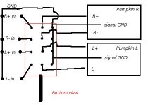
lykkedk said:This is how i do it... correct ?
Jesper.
dunno for your pcb - but for mine correct way is like this
Attachments
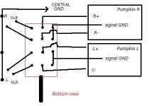
quote from ZenMod:
Thank's for the correction on my attenuator schm.
Well i tried to hook it up, the way you suggested, and some hum dissapeared.
look at zenmod's attennuator schm. here
I made a 'star' connection in middle of chassis (not connected to that) from that 'star' connection wires are going into these point's.
1 wire ---> pwr gnd Right channel
2 wire ---> pwr gnd Left channel
3 wire ---> signal gnd Right channel
4 wire ---> signal gnd Left channel
5 wire ---> comming from input gnd
The god thing is, that now my 4deck work's as good as my 2deck-stereo pot. 🙂
But still having that strange -in to GND problem... If i deattach the -in wire comming from attenuator, the is dead-quiet! ... But when -in is attached to attennuator there is comming some humming... really annoying. Donno what the problem is. Seem's to me, that it's some grounding issue...
Because when -in is connected to gnd via attennuator the is becoming very sensitive.. e.g when i touch some part's you can hear it. All that dissapears when disconnecting -in... something i didn't noticed before. I must say, that i didn't try it on my F4's this testing is done with my LeachAmp, there is ofcause the possibillity that there is no humming when connected to F4... but i sure would like to solve that problem anyway.
Jesper.
dunno for your pcb - but for mine correct way is like this
Thank's for the correction on my attenuator schm.
Well i tried to hook it up, the way you suggested, and some hum dissapeared.
look at zenmod's attennuator schm. here
I made a 'star' connection in middle of chassis (not connected to that) from that 'star' connection wires are going into these point's.
1 wire ---> pwr gnd Right channel
2 wire ---> pwr gnd Left channel
3 wire ---> signal gnd Right channel
4 wire ---> signal gnd Left channel
5 wire ---> comming from input gnd
The god thing is, that now my 4deck work's as good as my 2deck-stereo pot. 🙂
But still having that strange -in to GND problem... If i deattach the -in wire comming from attenuator, the
is dead-quiet! ... But when -in is attached to attennuator there is comming some humming... really annoying. Donno what the problem is. Seem's to me, that it's some grounding issue...Because when -in is connected to gnd via attennuator the
is becoming very sensitive.. e.g when i touch some part's you can hear it. All that dissapears when disconnecting -in... something i didn't noticed before. I must say, that i didn't try it on my F4's this testing is done with my LeachAmp, there is ofcause the possibillity that there is no humming when connected to F4... but i sure would like to solve that problem anyway.Jesper.
lykkedk said:............
gimme pics ,drawings , whatever ;
you must have ground loop somewhere .
gimme pics ,drawings , whatever ;
you must have ground loop somewhere .
Yep... groundloop it must be! --- but no piccie's today, cause children bring along digicam on a weekendtrip 🙂
I realise, that i did not use the 'coax shield' in coaxcable. it might be the problem.
The coax i use is a 3wire+shield cable, containing red, black, yellow. + shield.
I use the black wire as GND, red is for +connection's and yellow is -connection's. The shield connection, i just leave as it is at end of cable's... I just looked at your'e grounding schm. HERE
And see that the shield is connected at the PCB (which i didn't do so far)... this might could be it ???
Will be back when rewiring once more ! 😉 Not tonight for sure 😀
Jesper.
- Status
- Not open for further replies.
- Home
- Amplifiers
- Pass Labs
- Pumpkin preamp - More Boring Making Thread