jacco vermeulen said:
.....
This marble doesn't roll down well in my empty skull, care to BS ?
....
almost internal joke - sp300B made a mistake - putin' matched IRFs in Shunty .......... ya know - workin' all day long, soldering when kids (and wifie ) are sleeping .......
jacco vermeulen said:
.....
(me thinks he needs a showcase display to complement his travelling salesman suit for the ZZ-Mop world tour)
...
😡
 😡
😡 
jacco vermeulen said:
.....
Mmm, a Pass Dee-Idiot-Thang sticker would be more suitable

lykkedk said:... Finalv1.0 (opensource)
Jesper.
Very nice work.
Is it plexi, on the top?
(or did you just apply Jacco's blur kunst 😀 ?)
MANU
Originally posted by jacco vermeulen
Me just noticed you have the 100VA/50Vac model, (suppose you obtained one from Farny)
Me experience with glued core transformers is okidoki, Dagnall is a trannie co. from the jolly good show UK days.
Good value for meunie, + nice and small.
Thx - that helps curing my Angst I could have the wrong part...
Manu
jacco vermeulen said:
....
Planned any shielding for that transformer, Manu-sausalito ?
(ps : these threads can do with a clearer definition of transformer Buzz)
🙂
It depends... Have to test if it will fit noise-wise in same chassis or not.
About shielding :
The only noise problem I had with my Aleph 5 was induced hum from trafo (toroids from schuro) and mecanical buzz (imagine there is a razor inside the amp).
First was cure with playing with orientation and placing a (1,5 mm) metal plate between trafos and circuit (in fact rest of amp) a plate of something I would say it is iron.
A friend of mine, working in an Art gallery was using it to shield TV monitors during an exhibition. After demontage, he gave me the plates. They looks pretty like iron but this friend pretends they were expensive and special for shieding purpose (anyway uMetal don't looks like that).
And it really works.
Second (buzz) was cured with buying new trafos.
(At this place I would like to ask if somebody knows a method to test the polarity of unmarked toroid secondaries).
(C'est vrai, ils sont bien les Dagnall?)
Manu
Manu said:
(At this place I would like to ask if somebody knows a method to test the polarity of unmarked toroid secondaries).
(C'est vrai, ils sont bien les Dagnall?)
Manu
two independent secs , and you need them as one - center tapped ?
in that case - connect (temporary ) two ends of these two secs ;
measure voltage between (now) free ends of secondaries ;
if you have ~ 0V , they are in contra phase ;
( so - just use other end of one sec for connecting in center tap)
if you have full voltage , they are in correct phase
However, it is possible to phase a transformer with a voltmeter alone. I use a Variac to apply a low voltage, but a series resistance can be used to limit the current in case of an unexpected short. Apply a voltage to one of the windings, here winding 1-2. We can arbitrarily assign a phase mark to one end of this winding, say terminal 1. Connect the other end of this winding to one end of the other winding. There are only two possibilities, that we have connected to the marked or the unmarked terminal, as shown. Now measure the voltage between terminal 1 and the free terminal of the other winding (this cannot result in a short circuit because of the high resistance of the voltmeter). If you find twice the applied voltage, then conditions are as at the left. If you find zero volts, then conditions are as at the right. Now the second winding can be marked, and the proper connections determined.
To phase the secondaries, measurements can be made in exactly the same way. One winding is marked arbitrarily, the other connected to its other end, and the voltage measured to the open terminal. The secondaries can be phased relative to the primary just as if they were more primary windings, provided low voltages are used and the turns ratio taken into consideration. In all these measurements, we make use of the fact that the phase relations can be only in phase or in antiphase, which give distinctly different resultant voltages.
To phase the secondaries, measurements can be made in exactly the same way. One winding is marked arbitrarily, the other connected to its other end, and the voltage measured to the open terminal. The secondaries can be phased relative to the primary just as if they were more primary windings, provided low voltages are used and the turns ratio taken into consideration. In all these measurements, we make use of the fact that the phase relations can be only in phase or in antiphase, which give distinctly different resultant voltages.
Attachments

Relay 5V
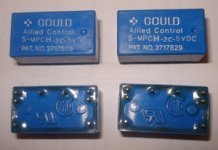
Hi, I have a bunch of relays as shown on picture. There are 5V rated.
Aim is to use it as Input selector for balanced (Relay is 2X2 type).
What kind of rectifier would be good to be prepared for runing the relays? To use separate trafo, grez and 7805 I guess would be the best option...
Hi, I have a bunch of relays as shown on picture. There are 5V rated.
Aim is to use it as Input selector for balanced (Relay is 2X2 type).
What kind of rectifier would be good to be prepared for runing the relays? To use separate trafo, grez and 7805 I guess would be the best option...
Attachments
Re: Relay 5V
Thanks Zen, Mod and Spavleski for answer about trafos.
Nice to have some engineers up there...🙂
Yes it works very well (don't forget little caps accross relay coil and protection diode).
Although I have heard that switching behaviour should be better if you use sistors to control the relay. You can use for instance some transitor arrays (most have protection diodes).
(But sure you certainly already know that)
🙂
manu
Thanks Zen, Mod and Spavleski for answer about trafos.
Nice to have some engineers up there...🙂
spavleski said:
What kind of rectifier would be good to be prepared for runing the relays? To use separate trafo, grez and 7805 I guess would be the best option...
Yes it works very well (don't forget little caps accross relay coil and protection diode).
Although I have heard that switching behaviour should be better if you use sistors to control the relay. You can use for instance some transitor arrays (most have protection diodes).
(But sure you certainly already know that)
Jacco : is there any parts-type or brand on this planet you don't know or never heard about?Nice, Allied C is an aviation gear brand
🙂
manu
boyz - ya both nutz ( yakk wonder - Jaccovitty isn't nutz , in this occasion ?!) ......
looking for schematic for implementation of few relays?
sec-graetz-1000uF-7805-10uF - selector - relays ;
each relay have just diode across coil ;
entire relay psu floating ;
what's fuss?
or I'm missing something ,as usual ?
looking for schematic for implementation of few relays?
sec-graetz-1000uF-7805-10uF - selector - relays ;
each relay have just diode across coil ;
entire relay psu floating ;
what's fuss?
or I'm missing something ,as usual ?
Attachments

ZM is spoking ...... (spikete spik)
that means that any end of relay PSU isn't connected to audio gnd ;
in engineering words - relay psu is isolated from audio psu
spavleski said:Schematic (Zen mode drawing...)...but Zen seems to be right...why bother with PCB. Zen what does exactly mean PSU floating.
that means that any end of relay PSU isn't connected to audio gnd ;
in engineering words - relay psu is isolated from audio psu
I thought to solder Relays near by XLR inputs (anap - as near as possible), just this diode and sistors make me  to understand why we need them + floating (most probably over the ground because of the avoiding inducing any hum...
to understand why we need them + floating (most probably over the ground because of the avoiding inducing any hum...Re: ZM is spoking ...... (spikete spik)
OK - So, whole PSU made for relays not to be conected to any ground. Correct?Zen Mod said:
that means that any end of relay PSU isn't connected to audio gnd ;
in engineering words - relay psu is isolated from audio psu
Re: Re: ZM is spoking ...... (spikete spik)
we'll solve that minor issues tomorrow via skipi or phone ....
anyway - point is that you must have either dedicated winding for that 5V psu , or dedicated small xformer ; when you make ordinary PSU of that ( written in my previous post) , you just not connect it anywhere in system , meaning on audio psu ; they are galvanic isolated or whatever ......... two completely independent circuits .
diode across each relay coil ( wired in anti-phase (orientation) A to + side of coil) is for peak suppression ......... ya remember what induction is 😉 ......... how eeeny weeeny ceiling bulb can be responsible for melting contacts on wall switch .......
when that psu is isolated - it's completely irrelevant which pole you choose sending to selector switch
spavleski said:OK - So, whole PSU made for relays not to be conected to any ground. Correct?
we'll solve that minor issues tomorrow via skipi or phone ....
anyway - point is that you must have either dedicated winding for that 5V psu , or dedicated small xformer ; when you make ordinary PSU of that ( written in my previous post) , you just not connect it anywhere in system , meaning on audio psu ; they are galvanic isolated or whatever ......... two completely independent circuits .
diode across each relay coil ( wired in anti-phase (orientation) A to + side of coil) is for peak suppression ......... ya remember what induction is 😉 ......... how eeeny weeeny ceiling bulb can be responsible for melting contacts on wall switch .......
Manu said:Yes.
Simply that :
(Better switch 5V not GRd may be.)
when that psu is isolated - it's completely irrelevant which pole you choose sending to selector switch
spavleski said:
I hope that you bought few male (heiss) ones , for outputs ............
- Status
- Not open for further replies.
- Home
- Amplifiers
- Pass Labs
- Pumpkin preamp - More Boring Making Thread