Hello Fotious,
Thank you for sharing this most elegant design. Yes, large heat sinks to accommodate low impedance loads like headphones makes sense. I hope it's safe to assume that no heat-sinks would be required to drive a power amp with an input impedance of 47K Ohms.
Best regards,
Obe1
Thank you Obe1. Of course, it is child's play a load of 47KΩ for the output of preamplifier. In the current project, i use in the output MJE172-182 with Ic = 3A. If you want more power, you could use MJE234-235 with Ic = 4A. If you want a slightly improvement in bandwidth, you could use BD139-140 with Ic = 1.5A.
Best Regards
Fotios
Congratulations Fotios.
You are always amazing me with your Passion for Perfection.
Thank you very much fellow 🙂 for your kind words. You are very polite.
Fotis
I checked the bandwidth of discrete in both configurations, either as voltage follower (Av=1 or 0dB) or as non-inverting with voltage gain +6dB. I attach a merged graph of both curves to make your comparison. The blue curve indicates the bandwidth in non-inverting config. (Av=+6dB) while the purple curve indicates the bandwidth in voltage follower config. (Av=0dB). You can see that the bandwidth of discrete configured as voltage follower extends beyond 1MHz, nearby 2MHz (+/-0dB, then starts to drop and the reference -3dB point is at 6MHz). In non-inverting configuration with Av=+6dB, its bandwidth is linear up to 400KHz (+/-0dB), then starts to drop and the reference -3dB point is at 1,5MHz. That is not so bad, so - IMHO - you can use it for the voltage gain of +7 to +10dB that you wish, without significant loss in performance 🙂Can I do anything (change something) so that gain is 7 to 10 dB?
Here the graph
Attachments

Last edited:
Ok thanks fotios, but as a stated I am beginner to me that curves are practically nuclear physics , you don’t need to spend your time simulating for 6db,10db. I just see a simple schematic #1, and I need preamp so, asked a few questions. And now one? can I change anything in that schematic to get 6dB,10dB and will it work well. Thanks anyway
In my eyes, you appear to be sufficiently experienced 😉. So, curves can tell you useful things. Indeed, the circuit of this discrete is a child of simulator. The workbench tests that i did with real instruments saw that prediction of simulator, was by 99% correct. Maybe this can give you an answer in your last question. Values of parts in schematic #1 are optimized with extensive - up to death! - use of simulator. So, it is good to keep the original values of parts presented on the schematic. You could not get more voltage gain by changing anything inside the circuit of discrete. This can be done only by changing the shape of external feedback network. You can play further, with different configurations of discrete and the associated parts needed to form the external feedback in each instance. Please, let me know if you need a schematic indicating the shape of a voltage gain stage and the values of associated parts.Ok thanks fotios, but as a stated I am beginner to me that curves are practically nuclear physics , you don’t need to spend your time simulating for 6db,10db. I just see a simple schematic #1, and I need preamp so, asked a few questions. And now one? can I change anything in that schematic to get 6dB,10dB and will it work well. Thanks anyway
Thank you
Fotios
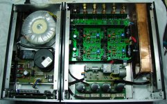
Join of two cases
Considering the resources and available tools, true craftmanship.
Makes a change, the most affordable amp-core parts, combined with a meticulous execution.
Hi im very interested in breadboarding this circuit. Can i expect a power on/off thump tho? Thats usually a deal breaker for me on whether i end up housing the build or not
Ive been enjoying this circuit a lot since building it a while back. Im wondering though if there will be a performance increase if the diode strings of the ccs were to be bypassed with an elcap (100uf?) like you see in many common circuits
Hi. Could i get this made to work with +-30v supply? If so is it just the current mirror resistors (47k) that has to be raised? Thanks
HiHi. Could i get this made to work with +-30v supply? If so is it just the current mirror resistors (47k) that has to be raised? Thanks
Yes, you can do that. Regarding the CM resistors, you have to experiment a bit to obtain a similar current as is the original.
Hi, i rebuilt this circuit of yours (which has become my permanent favorite btw 🙃) with 2n4401/4403 pair. However my rail voltages are +/-25, exceeding the 40v vce of the bjts. The circuit works fine. Am i in danger? 😅
Hi,
From a rough view, all transistors are biased in less than 4 Vdc, so there is no risk. However, you should note that 2N4401 has a different hFE (e.g. 100-300 @ Ic=150mADC, Vce=1VDC) compared to BC550C (e.g. 420-800 @ Ic=2mADC, Vce=5VDC) so the dynamic characteristics of the module will be changed. I mean the bandwidth, slew rate, etc. So it is a subject of your own sound taste 😉.
From a rough view, all transistors are biased in less than 4 Vdc, so there is no risk. However, you should note that 2N4401 has a different hFE (e.g. 100-300 @ Ic=150mADC, Vce=1VDC) compared to BC550C (e.g. 420-800 @ Ic=2mADC, Vce=5VDC) so the dynamic characteristics of the module will be changed. I mean the bandwidth, slew rate, etc. So it is a subject of your own sound taste 😉.

Thank you fotios and thank you more for this wonderful circuit.
I did build one with zetex bjts which sounded amazing but during this semiconductor drought we must do with what we can 😆
My next idea- run this circuit at +/-45v with maida regs 😎😎
For that would you recommend 2n5551/5401 or else?
The outputs for mine are bd139/140
I think the bias resistors for 45v would have to be 82k ohm(?).
Ive been tinkering with your wonderful circuit some more and heres what i have atm. Could it be possible to sim this or just speculate for me if the stability has been compromised? Soundwise it doesnt seem so. 🙂
Changes are-
output inclusive 2 pole comp (47pf & 100pf) ((to me more 'musical' sounding than the single pole comp))
Reverted to typical diode temperature protection (just couldnt make the layout look 'right' with your circuit)
RC filters to output bjt base (47ohm 100pf)
Grounded the vas buffer with 300ohm to collector.
The last modification is what worries me because its a significant circuit change. Soundwise it was an improvement. The background became darker and everything more smooth sounding. At first it was grounded with 33ohm and then when i raised it to 300ohm the bass became more prominent.
Would love to know what ive done, haha.
- Home
- Source & Line
- Analog Line Level
- Preamplifier from Lineup & Fotios for fun