Thank you Luke, you are very kind.wow that's very professional. Nice work Fotios!
More pictures
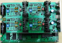
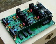
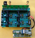
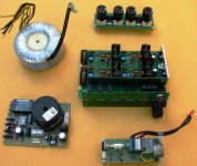
A whole stereo preamplifier, whose the heart are the four discrete BisBos OPAs, is implemented on this 190 X 135 mm PCB. The two front OPAs - behind the two large foil caps - form a stereo input buffer in voltage follower arrangement with unity gain. It should be noted that, this first stage can be easily modified as non inverting with any desirable gain by adding simply one resistor and one electrolytic cap in each channel. The two rear OPAs, form a stereo unity gain inverter circuit. Thus the preamplifier provides both single and balanced outputs. At the rear end, it is the voltage regulator-stabilizer circuit implemented by two LM317-337 followed by two common base transistors. On the same PCB, are mounted the input select and the mute Latching type relays. The vertical PCB transfers the commands from the microcontroller unit to the Latching relays, so digital tracks are separated-isolated from analog tracks. There are 3 gold pin headers. The one at the corner of PCB is for connecting a fourth input (in our case a Phono stage) instead the two at the middle are for connecting the motorized ALPS volume pot which is mounted on a separate PCB in which are included the H-Bridge and the auxiliary pot which tracks the rotation angle of ALPS and transfers it to the microcontroller.
The parts used are of high quality: All resistors are Vishay Sfernice MRS25, caps are either SCR, WIMA, Cornell Doubilier and Panasonic ECA. Small signal transistors are BC550C-560C and mid power are MJE172-182. Latching relays are OMRON G6AK-234P with Silver-Palladium-Gold contacts.
Attachments
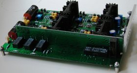
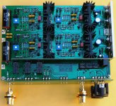
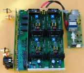
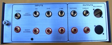
One week ago, i have completed the I / O sockets mounting patch board. In the pictures, you can see that i have soldered just two pairs of RCA sockets and a pair of XLR (all Neutrick). The first RCA pair is the CD input and the second is the Single Output, while the two XLRs are the Balanced Output. It remains only a PCB for the mounting of power supply reservoir capacitors (2 X 6800μF per channel) which are some big and could not be contained on the main Preamplifier PCB. The rest non soldered pads from the left, are: DVD IN - LINE IN - RECORD OUTPUT.
Attachments
Last edited:
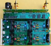
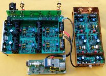
In these pictures, you can see the Preamplifier joined with its companions: The volume control unit and the Phono Stage. I had the chance to make some audition tests with vinyl records and CDs. To my ears and for the possibilities of my speakers Mission 780, the sound is quite good. Mids and Highs are neutral without colorations and screamings. Lows and Low-Mids are amazing good (that is the main benefit of discrete implementations against ICs), very tight and warm. The noise floor is very low (my estimation is about -90dB by hearing the output with my headphones in absolute silence).
Attachments

Great construction Fotios! Really nice to see!
When will you have the complete system housed?
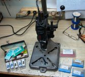
Thanks a lot Andrew for your kind words. You know probably that i make the metal cases for my projects, in home. I have a mitre saw, a hand operated milling machine and some aluminum sheets (2mm-3mm-4mm thick). I have in my mind a metal housing formed by two separate boxes (one for the transformers and the control unit and one for the preamplifier) joined together. It is some complex, but i like very much compact constructions. From my experience with discrete stages - so far - i know that are very sensitive (compared to ICs) and easily infected from any noise source (e.g. transformers). This is due to their "intrinsic" gain ability and their extreme bandwidth when are working in unity gain configuration, although we restrict these by using compensation networks. So, the metal casing needs big care and study.
By any way, i think that i will have ready the housing in one month from now.
Fotios
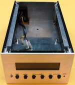
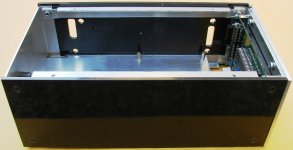
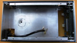
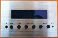
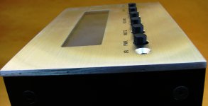
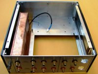
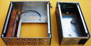
😀😀😀 OK, OK... I know that in 23 April i said that i will have ready the metal case in one month . Now it is 19 June, so finally i needed 2 months. Before the assembling of the whole unit, i would like to present the individual parts in pics. In general, the whole construction is formed by 3 separate cases joined but galvanically isolated between them. The basic material used is 4 or 2 mm thick aluminum sheet. Everything is hand made and home made. Side panels are painted with black-metal acrylic spray. Markings are obtained with Letraset Transfers or Letraset Shafmat film and are coated with Talens clear varnish (it is absolutely transparent, strong and has very good adhesion on aluminum) for protection from scratches. Both cases include sub-chassis for mounting the pcbs and parts, so as top and bottom covers can be removed easy for e.g. service or upgrade routines.
Attachments
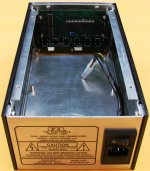
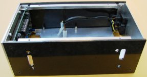
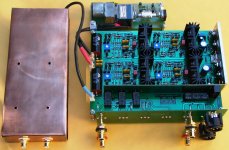
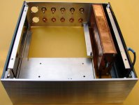
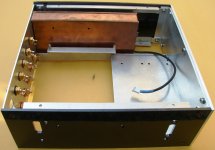
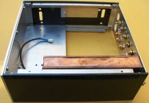
Here is the second case in which included the analog signal processing - routing circuits. The copper case, is the phono (RIAA) preamplifier which is also galvanically isolated from the main case.
Attachments

A few questions about a preamp I am a relatively new
1. Can It be done without input capacitor?
2. What is the gain of preamp?
3. Base of Q2 is going through 1K/220pF to output BJT?
4. Only 22pF is in front of an input to the ground
Thanks folks
1. Can It be done without input capacitor?
2. What is the gain of preamp?
3. Base of Q2 is going through 1K/220pF to output BJT?
4. Only 22pF is in front of an input to the ground
Thanks folks
A few questions about a preamp I am a relatively new
1. Can It be done without input capacitor?
2. What is the gain of preamp?
3. Base of Q2 is going through 1K/220pF to output BJT?
4. Only 22pF is in front of an input to the ground
Thanks folks
1. Yes, the big capacitor of 4.7μF connected between input and attenuator (volume potentiometer) could be omitted. The same for the 22pF capacitor connected across the wiper of volume potentiometer and GND. The reason is the big value (100 KOhms) of potentiometer, which infects the linearity of the buffer stage when is turned at intermediate places. If you use a small value potentiometer (say between 1 to 5 KOhms) you should be able to remove these two capacitors. I had in my stock only 100KOhms potentiometers, for this reason i did this trick.
2. Take a look please at the block diagram of post nr. 2 where you could see that the discrette OPA is arranged as voltage follower forming a non-inverting buffer. So, its gain is 1 (unity gain).
3. Yes, base of Q2 is the inverting input of LTP and is connected thru the feedback network (1K / 220pF) to the output of buffer stage.
4. For the 22pF capacitor, i gave an explanation previously.
Thank you
Fotios
Hello fotious,
Bravo !
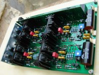
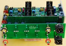
In post #2 you have a photo of your trial / prototype design with no heat-sinks on the BJTs. In post #42 you have a photo of your finished design with BIG heat-sinks on the BJTs. I've never seen a solid-state op-amp that generated a lot of heat. Why the big difference?
Best regards,
Obe1
Bravo !
In post #2 you have a photo of your trial / prototype design with no heat-sinks on the BJTs. In post #42 you have a photo of your finished design with BIG heat-sinks on the BJTs. I've never seen a solid-state op-amp that generated a lot of heat. Why the big difference?
Best regards,
Obe1
Hello fotious,
Bravo !
In post #2 you have a photo of your trial / prototype design with no heat-sinks on the BJTs. In post #42 you have a photo of your finished design with BIG heat-sinks on the BJTs. I've never seen a solid-state op-amp that generated a lot of heat. Why the big difference?
Best regards,
Obe1
Thanks Obe1 for your kind words. Heatsinks on the output transistors give in preamplifier the ability of driving low loads like headphones.
Thank you
Photius 🙂
Hello Fotious,
Thank you for sharing this most elegant design. Yes, large heat sinks to accommodate low impedance loads like headphones makes sense. I hope it's safe to assume that no heat-sinks would be required to drive a power amp with an input impedance of 47K Ohms.
Best regards,
Obe1
Thank you for sharing this most elegant design. Yes, large heat sinks to accommodate low impedance loads like headphones makes sense. I hope it's safe to assume that no heat-sinks would be required to drive a power amp with an input impedance of 47K Ohms.
Best regards,
Obe1
Can I do anything (change something) so that gain is 7 to 10 dB?
Yes, you can do this. Look please at the PCB layout in post #38, there is the option of using the discrete either as voltage follower or non-inverting amplifier. The associated parts to this, are C5 - C9 = 470μF/35V electrolytic and resistors R8 - R28 = 8.45KΩ. Resistors R9 - R27 must be changed to 8.45KΩ and capacitors C6 - C10 to 15pF. After this, the gain of discrete will be "2" = +6 dB. It should be noted, that the bandwidth of discrete is reduced at around 350KHz (if i remember well, i will check it to confirm you) when is working to provide voltage gain. More gain, less bandwidth. Its original bandwidth with gain = 1 or 0dB is almost 1MHz, so if you don't need voltage gain it is better to use it as voltage follower.
Thank you
Fotios
- Home
- Source & Line
- Analog Line Level
- Preamplifier from Lineup & Fotios for fun