New VAS simulation.
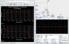
As you see in the image 1 your version is not enough compensated.
There is an overshoot both in the AC Analysis and the oscilloscope square wave.
It is not to bad, but it is not what I want.
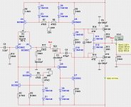
I have changed some component values to make a perfect square wave.
You can see my changes in image 2.
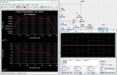
And so the result after changes in image 3.
The distortion, THD, is a little bit worse in your version. But not too much at all.
As you see in the image 1 your version is not enough compensated.
There is an overshoot both in the AC Analysis and the oscilloscope square wave.
It is not to bad, but it is not what I want.
I have changed some component values to make a perfect square wave.
You can see my changes in image 2.
And so the result after changes in image 3.
The distortion, THD, is a little bit worse in your version. But not too much at all.
Attachments

What is your headphones?this is probably ideal for most line level needs. however i use my preamp for headphones sounded excellent.
What impedance do they have?
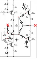
You have really used 1k for R12?Hi. Sorry, this is about the best i can do atm. I have not learned how to draw on a program, even tho i spend 100s of hours on eagle pcb design for fun 😅.
The added caps are all 100pf. Red 'x' indicates the feedback resistor node from output to 2 pole comp. 47ohm base resistors for output bjts.
I had a lot of 139/140-16 on hand so i used them.
If you say mje's perform better i will want to order them.
For me I have used 150 or 220 to set the bias in output.
R12 as 1k gives a voltage drop more than 5 Volt.
Attachments
Thanks lineup. Very cool!
For the corrected version isnt the cap value too high, harming the bandwidth? I feel like two pole comp was a step backward at this point.
Also would it be possible for me to have that file? And what program is it? Its time i learn.
For the corrected version isnt the cap value too high, harming the bandwidth? I feel like two pole comp was a step backward at this point.
Also would it be possible for me to have that file? And what program is it? Its time i learn.
Oh also ive replaced d7 d8 with 3k ohm in my build.
R12 is a trimpot set around 120ohm. Output resistors are 10ohm instead of 22ohm.
The phones are akg k701, 63ohms. 47ohm series resistor is present in my preamp
R12 is a trimpot set around 120ohm. Output resistors are 10ohm instead of 22ohm.
The phones are akg k701, 63ohms. 47ohm series resistor is present in my preamp
You got the point at last. Professional designers follow some standard rules (I don't claim this role though), they take care to keep all transistors within their linear region by applying a suitable biasing on each one, and they try to keep the current of each branch constant using thermal compensation where is needed. The simulator is very helpful, as e.g. calculates all D.C. points but you should know if those are suitable for each one of the transistors you are using. By changing the values of resistors or substituting diodes with resistors to chance, you could cause high THD, instability and thermal issues, etc. although you believe that "it sounds good", as the sound taste is completely subjective. BTW an excellent and freeware simulator is the LTspice, with schematic capture and waveform viewer.I think i should stop here and wait for someones professional input. Without any knowledge i am shooting blind at this point.