It is nice to see your work.
Although it makes the amp a little bit more complicated.
The important is however that it sound as good as possible.
Have you find the output transistors? MJE182 MJE172. Can be replaced with BD139 BD140
In my SPICE I have everything needed. Including MJE182 MJE172
Perhaps I will simulate.
Although it makes the amp a little bit more complicated.
The important is however that it sound as good as possible.
Have you find the output transistors? MJE182 MJE172. Can be replaced with BD139 BD140
In my SPICE I have everything needed. Including MJE182 MJE172
Perhaps I will simulate.
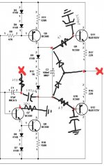
Could you make a more clear schematic? Has got several questionmarks..Ive been tinkering with your wonderful circuit some more and heres what i have atm. Could it be possible to sim this or just speculate for me if the stability has been compromised? Soundwise it doesnt seem so. 🙂
Changes are-
output inclusive 2 pole comp (47pf & 100pf) ((to me more 'musical' sounding than the single pole comp))
Reverted to typical diode temperature protection (just couldnt make the layout look 'right' with your circuit)
RC filters to output bjt base (47ohm 100pf)
Grounded the vas buffer with 300ohm to collector.
The last modification is what worries me because its a significant circuit change. Soundwise it was an improvement. The background became darker and everything more smooth sounding. At first it was grounded with 33ohm and then when i raised it to 300ohm the bass became more prominent.
Would love to know what ive done, haha.
Hi. Sorry, this is about the best i can do atm. I have not learned how to draw on a program, even tho i spend 100s of hours on eagle pcb design for fun 😅.
The added caps are all 100pf. Red 'x' indicates the feedback resistor node from output to 2 pole comp. 47ohm base resistors for output bjts.
I had a lot of 139/140-16 on hand so i used them.
If you say mje's perform better i will want to order them.
The added caps are all 100pf. Red 'x' indicates the feedback resistor node from output to 2 pole comp. 47ohm base resistors for output bjts.
I had a lot of 139/140-16 on hand so i used them.
If you say mje's perform better i will want to order them.
Attachments
BD139/140 are good. Noneed to change them.
It might even be an improvement from MJE182/172
It might even be an improvement from MJE182/172

There was a dramatic change in sound when i connected the vas emitter to gnd and then dramatic change once more when i added 200ohm ground lift. Would love to know what is going on there.
Because other changes i have made are common add-ons, whereas the vas is now something i have never seen before.
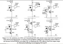
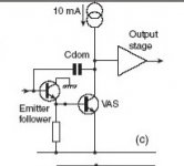
But i understand if we replace the string of diode it becomes this classic arrangement. (C)
Because other changes i have made are common add-ons, whereas the vas is now something i have never seen before.
But i understand if we replace the string of diode it becomes this classic arrangement. (C)
Attachments
They sound good! 😁BD139/140 are good. Noneed to change them.
It might even be an improvement from MJE182/172
If I should simulate I need to know eventual input cap and resistor.
Also on the other pole I need to know feedback resistor divider and cap, which sets the gain.
Also I like to know power supply voltages.
Also on the other pole I need to know feedback resistor divider and cap, which sets the gain.
Also I like to know power supply voltages.
Last edited:
Input cap is 2.2uf, 100k ohm to gnd. Then 2.7k ohm, then 220pf to gnd.
Feedback is 30k/10k ohm.
Voltages are +/-25v
Feedback is 30k/10k ohm.
Voltages are +/-25v
100k and 30k is a mismatch. Gives a lot DCoffset on outpur.
Either use 30k input and 30k feedback
Or use 100k input and 100k feedback
Also from the 10k a capacitor, say 10uF, to the gnd, if you use 30k/10k feedback
Either use 30k input and 30k feedback
Or use 100k input and 100k feedback
Also from the 10k a capacitor, say 10uF, to the gnd, if you use 30k/10k feedback
Hi,
That is the original Dean Jensen 918 discrete circuit with 2N5401/5551. It also includes the output DC offset calibration circuit (R1, D1, VR1, D2, R2) and the input clamping diodes D3 and D4. All diodes are 1N4148. Using BC550C/560C and BD139/140 you could obtain a better bandwidth product. However, the THD performance is the same with either BJT combination, for the given circuit, all tried in simulator, but for the difference in sound taste not have a clue.
Last edited:
Yes im using 47uf to gnd. Thank you for those tips. Impedance matching... a detail that matters for sure 😁
Any news on the sim?
Meanwhile I replicated the arrangement shown earlier by replacing the 2 zeners with 3k ohm.
The sound is different again. Smoother but less bass.
I think i should stop here and wait for someones professional input. Without any knowledge i am shooting blind at this point.
Any news on the sim?
Meanwhile I replicated the arrangement shown earlier by replacing the 2 zeners with 3k ohm.
The sound is different again. Smoother but less bass.
I think i should stop here and wait for someones professional input. Without any knowledge i am shooting blind at this point.
Attachments
You should be careful regarding the closed-loop gain and the configuration of discrete. The best GBP is obtained in voltage follower arrangement, i.e. without gain (0dB). You could do this by connecting the output to the inverting input with a 1K resistor and feeding the signal to the non-inverting input. In inverting arrangement the GBP will be half. If you apply voltage gain to discrete the GBP is also reduced.
In the 1st pic of the 2nd post, a non-inverting with gain=1 is shown. Anyway I quote again the pic
You might use only M.F. resistors for good THD+N performance. On your board, there are a lot of C.F. resistors.And of course the action shots!
that choice is intentional. i am not chasing after the lowest distortion but rather pleasant distortion 😉
any word on how the new vas simulates?
any word on how the new vas simulates?
this is probably ideal for most line level needs. however i use my preamp for headphones and also phono amps so a bit of gain is needed. in the past i used ne5534 and 797 in that buffer config and they sounded excellent.In the 1st pic of the 2nd post, a non-inverting with gain=1 is shown. Anyway I quote again the pic
View attachment 1135541
- Home
- Source & Line
- Analog Line Level
- Preamplifier from Lineup & Fotios for fun