I have some bascom code that I use for those Bourns encoders with built in switches and leds
It is not interrupt driven
Do you want it? It was used on the Elektor dsp radio using the atmel mega and si4735
It is not interrupt driven
Do you want it? It was used on the Elektor dsp radio using the atmel mega and si4735
Sure, send me a txt file or whatever is human readable and I will check it out and test it.
Appreciated.
John
Appreciated.
John
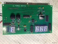
Here are the Gerbers, BOM, and updated PDF files of the Display board.
Attachments
Some snips of code
reading of the encoders is done using a timer interrupt routine.
reading of the encoders is done using a timer interrupt routine.
Code:
Dim Encoder1 As Integer
Dim Encoder1old As Integer
Dim Code1 As Byte
Dim Code1old As Byte

Config Timer0 = Timer , Prescale = 8
On Ovf0 Tim0_isr
Enable Timer0
Enable Interrupts

Portc.1 = 1                                                 'Encoder
Portc.2 = 1


  If Am = 1 Then
    If Encoder1old <> Encoder1 Then
      If Memoryaktiv = 1 Then
        If Ammemorymax > 0 Then
          If Encoder1 > 0 Then Ammemorypos = Ammemorypos + 1
          If Encoder1 < 0 Then Ammemorypos = Ammemorypos - 1
          Encoder1old = 0
          Encoder1 = 0
          If Ammemorypos > Ammemorymax Then Ammemorypos = 1
          If Ammemorypos < 1 Then Ammemorypos = Ammemorymax
          Locate 2 , 1
          Lcd "M"
          Lcd Ammemorypos
          Lcd "  "
          Fam = Ammemory(ammemorypos)
          Disable Interrupts
          Am_tune_freq
          Encoder1old = Encoder1
          Enable Interrupts
          Locate 1 , 1
          Lcd Fam
          Lcd " "
            If Ammemorypos < 21 Then
            Text1 = Amtext(ammemorypos)
            Locate 2 , 7
            Lcd Text1
           End If
        End If
      Else
        Freq = Encoder1 * 5
        If Band = 1 Then Freq = Encoder1 * 1
        If Band = 2 Then Freq = Encoder1 * 9
        Encoder1old = 0
        Encoder1 = 0
        Fam = Fam + Freq
        Print #1 , Fam
        Disable Interrupts
        Am_tune_status_stop
        Waitms 1
        Am_tune_freq
        Enable Interrupts
        Locate 1 , 1
        Lcd Fam
        Lcd "  "
        Waitms 300
      End If
    End If
  End If

Tim0_isr:
  Code1 = Pinc
  Code1 = Code1 And 6
  If Code1.2 < Code1old.2 Then
    If Code1.1 = 1 Then Encoder1 = Encoder1 + 1
    If Code1.1 = 0 Then Encoder1 = Encoder1 - 1
  End If
  Code1old = Code1
ReturnWell I read through the code and unfortunately it won't work any better than the current code, but thanks for sending it along to learn.
recently I came across an article about interference from relay coils - and the reason for "pop" on the working contacts of the relay (loaded with high resistance) may be the capacity of the coil and the associated temporary increase in current when switching on the relay - the author of the article claims that it can be significantly reduced (eliminated ) using a resistor (33Ohm) in series with the coil ... (of course, it is about the parasitic capacitance of the coil circuit in the relay and the article was about such interference in audio relay circuits)I spent most of the day today debugging the software and testing hardware, and it is working correctly, finally. I will double check the PCB layouts again tomorrow and order boards. And another order of parts. Once I build up a set of boards I can fine tune the software while listening to a square wave until the pop is gone.
I am changing the relays from the LSB to MSB when turning up and MSB to LSB when turning down the volume, hopefully this method will work first time.
Attached is a copy of the code for anyone with a case of insomnia.
Last edited:
Can you give the link to that article, it might be an interesting read. The relay has an internal resistance of 178 ohms which for the 5 volt source gives a 28 milliamp current which IS the operating current of the relay. Adding a 33 ohm resistor in series with the coil gives 211 ohms which allows 24 milliamps of current which is PROBABLY enough to pull in the relay. I don't know that dropping 4 milliamps of current would make a difference but it might be something to test if I feels like hacking up a board. The capacitance and inductance of the relay coil gives a voltage spike when it releases which is why there is a diode across the coil and I think there may also be a diode built into the relay.
this article is not available online. I could send you a pdf with this article but you would have to translate it from Polish... (mag : Elektronika Praktyczna 3/2022Can you give the link to that article, it might be an interesting read. The relay has an internal resistance of 178 ohms which for the 5 volt source gives a 28 milliamp current which IS the operating current of the relay. Adding a 33 ohm resistor in series with the coil gives 211 ohms which allows 24 milliamps of current which is PROBABLY enough to pull in the relay. I don't know that dropping 4 milliamps of current would make a difference but it might be something to test if I feels like hacking up a board. The capacitance and inductance of the relay coil gives a voltage spike when it releases which is why there is a diode across the coil and I think there may also be a diode built into the relay.
"Notatnik konstruktora" - "Constructor's notebook " and title "reduction of interference introduced by relays" it's a note rather than an article about specific interference in relays . but exactly about "pop" in relay's in audio...🙂 )
in short: the author has been associated with the audio industry for years. Especially the selectors, the volume control. He often had signals from customers that "something is knocking, crackling etc. Finally, he noticed that the relay coil consumes much more current than nominal when it is switched on. Hence the conclusion about the coil circuit capacity. The measured oscillations on the 51 kOhm resistor connected ONLY to the relay contacts amounted to 184 mV!this article is not available online. I could send you a pdf with this article but you would have to translate it from Polish... (mag : Elektronika Praktyczna 3/2022
"Notatnik konstruktora" - "Constructor's notebook " and title "reduction of interference introduced by relays" it's a note rather than an article about specific interference in relays . but exactly about "pop" in relay's in audio...🙂 )
(he showed it on the oscillogram) when turning on the relay. And he was expecting 0 ... in practice, the simplest solution is the resistance in series with the coil - to reduce the steepness of the coil current rise, it requires a slight increase in the voltage supplying the relays. or powering the relay's coils with current sources ... Author : Michal Kurzela
By Polish isn't so good. 🙂 Ah well, interesting theory though. I have some 4.5v relays that I can try someday with the resistor in series, just to see what happens.
Thanks, John
Thanks, John
Found an error in the BOM, the EEPROM should be a SOIC part but the part number was a DIP, the difference of a P or S in the part number.
I will give the BOM another scrub and repost.
Enjoying the rebuilt preamp immensely.
I will give the BOM another scrub and repost.
Enjoying the rebuilt preamp immensely.
Roy found a problem with the new Analog board in that the I/O connection pitch was set to 2mm and wanted it to be 2.54mm which is an easier connector to get and the plug for it doesn't cost and arm and a leg for the pins, sold separately. Also wanted a Pin 1 marker for the 24 pin header connection which btw goes on the top of the board. And I updated the power connector since there is no board under it feeding power up. So here is the updated gerbers. Still need to scrub the BOM then repost it.
Attachments
Good to have someone else go through the BOM, I have looked at it so long that I stop seeing the problems.
Roy has been going through the BOM and found a couple problems with the resistor Reference Designators on the resistors of the Display Board.
So, here is the latest update of the BOM.
Roy has been going through the BOM and found a couple problems with the resistor Reference Designators on the resistors of the Display Board.
So, here is the latest update of the BOM.
Attachments
So a little information on the new boards for troubleshooting. The Display board can be tested by itself then connected by a ribbon cable to the Analog board. Power up the board, the digital pins for volume, relays and display, are D3-D10, pins 6-13 on the Nano, they should all come up as LOW, 0.25 to 1.5v. The mute pin, D11, Nano pin 14, should be low. Input selection pins D16-D18, Nano pins 21-23, should be High, Low, Low. Measure from ground to the pins to see if you have the right outputs, if so then any problem with the volume display is in the Display circuit, check U4 the oscillator for output from pin 3, U7 should be toggling its flip-flops setting the last two address bits of the EEPROM and feeding U6 the clocked output of U7 to decode the two input on pins 2 and 3 of U6 to decode to 0-4 to turn on the LEDs one digit at a time, so rapidly they look like they are all on together. The inputs to the EEPROM Address line A0-A7 should not be changing and should match the relays so you can measure with a voltmeter. Address lines A8 and A9 address into the EEPROM with 00, 01, or 11 and are changing rapidly so need a scope to see or an AC Hz setting on the VOM.
Most other things are easy to follow on the schematic to troubleshoot. Any questions just bring them up here.
Most other things are easy to follow on the schematic to troubleshoot. Any questions just bring them up here.
John,
With apologies for not contributing sooner. Although subscribed to this thread, I have not received any notifications since the forum software was upgraded. I wasn't aware that you were implementing with an Arduino.
I have been developing my own preamp based on Arduino (and learned from your hardware implementations) and have written some code that I am happy to share. I also based my input on the Apple remote and rotary encoders. You seem not yet to be comfortable with the rotary encoder and the use of interrupts. For this use case I believe it its best to use interrupts. I attach some code that gives an introduction to using a rotary encoder for, for example, changing volume. I hope it helps.
I shall send you a private message if I can work out how to.
Regards
Geoff
Attachments
Hi Geoff,
I will look over your code. The problem is, I am using an Arduino Nano and it only has two interrupt pins. For this application I need one interrupt for the IR Receiver input and two for the rotary encoder. Since the IR Remote is more important I used one interrupt pin for that and turn off the interrupts in the encoder software. It works well if you don't turn the rotary encoder too fast, turning briskly but not too fast the counts up or down fine, too fast and it gets confused without the interrupts.
It might not be perfect but it does work well and the resistor attenuator is excellent sounding so I am very happy with my preamp sound.
I will read your code and see what else I can learn and maybe make an improvement.
Thanks,
John
- Home
- Source & Line
- Analog Line Level
- Preamp Control - Volume, input, mute, remote