"schematic diagrams attached with post 280 seem to suggest the order of MSB-LSB on the relay control bus is flipped between J5 on the digital board and J1 on the analog "
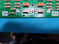
On J5 of the digital board Pin 1 is MSB and Pin 8 is LSB, U4 has bits 1-4 from Q0-Q3 outputs respectively, and U3 has bits 5-8. J1 on the Analog board Pin 1 is MSB and Pin 8 is LSB. If you look closely over Q1 there is text in gray that say LSB and over Q8 there is gray text MSB. A bit hard to see I know. Biggest fun is tracing the lines out of U3 and U4 as they cross the schematic. More than once I almost messed up in drafting the wiring.
Hopefully that clarifies things, if not, let me know and I will try to be more Illustrative. 🙂
If you look closely over Q1 there is text in gray that say LSB and over Q8 there is gray text MSB.
Thanks, John. That makes sense. I overlooked those in gray.
So I have parts coming Wednesday or Thursday to do some more testing on the ladder volume control analog board to see if I can't de-pop it. Also I created another Analog board with the digitally weighted resistor scheme, that never popped, that can drop right on to the digital board, same width 7" but only 6" long instead of 8". And I am trying some resistor values to keep the input load no lower than 640 ohms, which any peripheral can drive. And with half as many resistors it is a little cheaper to build, and possible sound better?
After more testing of each I will let you know the results and if good than I will post a BOM and gerbers.
After more testing of each I will let you know the results and if good than I will post a BOM and gerbers.
John,
In wiring up my version of the analog board (3.1) I have found that the form factor for the volume output easily fits the standard 2.54 mm single row non locking headers with the wire markings still showing. However, I am finding that the con housing can easily slip off because they are non-locking.
Installing a locking header, while still fitting in the space available, will cover the output polarities. In the picture below, I am using a common locking header (Mouser 538-22-11-2032) notice that there are no longer any visible polarity markings for the outputs. As the pinouts for each channel do not follow the same polarity pattern, this can be confusing. I would suggest moving the polarity markings further away from the header so that they are still visible. There seems to be plenty of room for that change on the analog board.
Regards,
Roy
Attachments

I can do that on the next rev of the board when we find out if it needs a fix for the pop.
Did you turn the transistors around and did they work then. Also, your relays were the 5v variety correct?
Did you turn the transistors around and did they work then. Also, your relays were the 5v variety correct?
The relays were the old ones, so they would have been 5V. I didn't bother to turn them around, I still had 10 of the original transistors from my first build and used then in one board. Everything came up fine putting the volume a 255 activated all relays and they came up just under 5V. I will be putting it in the system in a day or so. I have more coming from Mouser shortly that should complete my build on all three sets of boards.
Installed the 2N3904s on all three boards and had sucess getting output. Running 2V through the input of the volume control I was surprised how slowly the voltage ramped up. I expected it to be logarithmic, but I didn't seem to be getting appreciable output until the volume was set at 190-200 or so. I did a proof-of-concept test running it in front of my BOSOZ into my Alpha J and into some efficient test speakers found the normal listening level to be around 210 to 220 with DACs of both single ended and balanced input. I would have expected the ramp to begin a bit earlier and have a bit more granularity. The first 150 steps don't seem to produce any appreciable output at all.
There is an online calculator that gave me the resistor values. With 256 steps it probably has to start with less attenuation instead of -127 db to 0 db with .5 db steps.
We can play with the values to find more optimal values. At current values I listen at 190 step or so, I start hearing sound at around 125.
Yesterday I received by Digitally Weighted volume control board that drops onto the current digital board. Once built I can easily compare the two designs for sound quality and input loading, or output values.
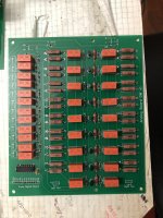
Tonight I finally got some time to troubleshoot the no sound problem from my right channel. While looking for the cause of a hum in my diy Aleph P preamp with my volume control I accidentally fried one channel. After pulling out the preamp board out and replacing the MOSFETs I put it back in and nothing. Pulled both channels and measured voltages starting with the good channel, then the bad channel. Started at the voltage input to the board it was good but right past the resistor of the RC filter was nothing. Found the power pulse burned the resistor without any visual clues or cracking, never saw that before. Replaced the resistor and it read good for voltage. Putting it back together then can test the volume boards more. The pop wasn't there last time and I now have the first version type board to try on control board. Will post a pic of the new board. Once tested and compared with the ladder design I will post gerbers.
Last edited:
Just spend a couple hours trying to find the reason for the pop at 127 to 128 and 191 to 192. Tried a diode across the main power supply and adding decoupling caps to the power supply right at the analog board. Didn't help. Tried caps across the diodes at the relays. Didn't help. Even tried removing the base resistor to the LSB transistor so the resistor is always in circuit for testing. Didn't help.
I did find that if the source is quiet then there is no pop, if you have a signal or any DC then it pops.
I have the input selection first, then the volume section, then the gain. The gain section input is capacitor coupled so something to try is moving the cap to between the input and the volume section. I may try to do input, gain, then volume which is how I did all the original testing and listening and didn't have a problem with it popping as the gain section of the Aleph P module and capacitor coupled in and out.
After I try all the final testing I will then try the digitally weighted volume board.
This is the exact behaviour I have described previously so the the volume reduction is temporary nulled thus volume is max at transitioning multiple relays at the same time. No effect when no signal present since max of zero is….zero but with a signal the music is at highest volume in the 10msec range duration with appears to sound like a pop! The way to reduce it:
1) zero crossing detector like in digital IC;
2) use different timing for switching the MSB relays so not all of them switches at the same time (this is what I have done). This way the volume cannot be at maximum during transition.
3) there should not be any significant DC present in the signal.
fab
I don't think that is it, with the relays I am using they take twice as long to pull in as they do to release so going from 127 which is the first 7 relays on then 128 is the MSB relay on with the other 7 turning off. If the release was slower then pull in then you could have all on for an instant but since the 7 release first before the 8th comes on it is not going full volume. So still looking into the why. Since it did not pop when the volume section was last that is more evidence it is not going full volume.
Well, I tried a couple more things to find the reason for the pop. I moved the volume section to different locations in the signal chain. No difference. Tried running a square wave through the volume section and found I could cause it to pop every time not just some times so the signal content matters.
Then I changed to the first design board, the digitally weighted resistors. It didn't used to pop but with a square wave even this board pops slightly.
Sonicly it is no better then ladder design. So I am going to use different resistors in the ladder design. Right now the values give 0 to -127 db in .5 db steps. Will test with .375 db steps for 0 to - 96 db, and .25db steps for 0 to -64db to find a more useable range. The curve is logarithmic to increases slowly then fast near the end. Will be using the Vishay Industrial grade resistors after having listened to them and having my audio business friend like the sound also.
I have tried a lot of experiments to find the reason for the pop going from 127 to 128 and haven't found a explanation for it. I know the Aleph P preamp uses the same configuration on the relays but uses a PIC to control the relays instead of logic chips. I have tried faster and slower chips but for the speeds we are using it wouldn't make a difference. So for personal use I can live with a pop, and if I rotate quickly through that volume it is barely annoying. It would not be good in a professional preamp as-is.
But I did try other resistor values to get the volume control into a more usable range. Instead of .5 db steps, changing to .25 db was an easy change. One set of 2 resistors has to change and the rest to the current resistors move down. It is a recommended change.
Attached is the updated BOM with the resistor values.
Attachments
I have been researching the pop issue for the relay controlled resistor volume control, and find the same configuration has been used many times, the differences are in the control scheme. It APPEARS the time from opening a relay to closing the next one needs to be longer than them reaction times of the relays. So, I can delay a relay pull in with passive components but it would also increase the release time so not a solution. Many of the implementations use a microcontroller to control the relay pull in and release timing. So I have come full circle from the original problem I was trying to resolve without programming, and now it looks like I will need to have a solution that requires programming. Oh well, if you can beat em, join em.
Good news is only the digital board would need to change and the Microcontrollers are cheap. Now I need to study and learn more to implement this change and figure out which is the best microcontroller for the task. At least I have been a programmer in my past. Anyone have a favorite microcontroller?
Good news is only the digital board would need to change and the Microcontrollers are cheap. Now I need to study and learn more to implement this change and figure out which is the best microcontroller for the task. At least I have been a programmer in my past. Anyone have a favorite microcontroller?
John,
When you bring a microcontroller into the system is there any chance that you would be able to offload the remote-control configuration options to programing? This would avoid the requirement of a dedicated apple chip for the remote and provide much more flexibility.
Regards,
Roy
When you bring a microcontroller into the system is there any chance that you would be able to offload the remote-control configuration options to programing? This would avoid the requirement of a dedicated apple chip for the remote and provide much more flexibility.
Regards,
Roy
Hi Roy,
That would be a possibility, but basics first, it would only control the resistor relays to start with, then can see about mute and input selection, then remote.
That would be a possibility, but basics first, it would only control the resistor relays to start with, then can see about mute and input selection, then remote.
John,
My reading of your volume ramp resister changes from the BOM is that you add four 340K and four 280R resistors and drop four 6.34R and half of the 10K resisters (four) and the rest get moved around. Is that correct?
Regards,
Roy
My reading of your volume ramp resister changes from the BOM is that you add four 340K and four 280R resistors and drop four 6.34R and half of the 10K resisters (four) and the rest get moved around. Is that correct?
Regards,
Roy
Correct. Most of the resistors get reused and only 2 values added and 2 dropped, but this puts the volume control range into a much more useable state with its logarithmic curve.
And, I have been going through the steep learning curve of using a microprocessor. It looks like all the digital board parts would be replaced by one Chip, or could use an Arduino Nano. Still studying. This is not going to be a quick change but once I have it down I can make several improvements.
And, I have been going through the steep learning curve of using a microprocessor. It looks like all the digital board parts would be replaced by one Chip, or could use an Arduino Nano. Still studying. This is not going to be a quick change but once I have it down I can make several improvements.
- Home
- Source & Line
- Analog Line Level
- Preamp Control - Volume, input, mute, remote