 .
.John,
I received my boards back today and am happy to report the boards and cable work as advertised. I tested all my other digital and display boards, and they were working correctly as well. I quickly went through and scratched out the "A" and "B" on my other display boards connectors and relabeled them with magic marker.
I then looked carefully at the cable that you had modified for me. I noticed that you had changed the orientation of B on the display board and found that that configuration worked correctly. The problem is that one of our sets of eyes is lying to us🙂.
To me, the blue pin is no longer oriented to the dot. The blue pin on the cable is coming in from the top of the board but the dot shows that the cable should be coming in from the center of the board. Please review the picture and see what you think.
Regards,
Roy
Attachments
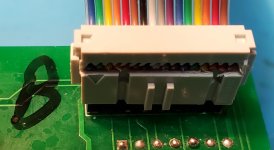
I see the problem, it is in the thought that the cable has to come out of the pin 1 SIDE to BE pin one but that is not the case. Look at the connector, the triangle points at the dot, the cable could come out of the bottom of the connector as it does now or out the top, pin 1 is to the left in the picture and so long as the blue wire is on that side your are good. Look into a connect that hasn't been press yet you will see the wire piercer doesn't care which side the cable comes out of.
Looking at the connector, I see what you mean. I was limiting myself to a subset of viable cable configurations. In other words, if I connected both sides blindly, I would have a 50% chance of getting it right rather than just the 25% chance I had assumed🙂. My other set of cables works fine but I guess I didn't beat the odds on one of the cables I sent you.
From looking at your mainboard schematic, it looks like you might be missing some functionality that could end up being crucial.
Lets say 00000000 is maximum attenuation and 11111111 is no attenuation.
What happens if you are at 01111111 and you turn up the volume by 1 step?
Remember that realys do not make/break instantly.
Then if you were really unfortunate all relays could be ON for short(1ms or so) while and you would now temporarily end up with 11111111 which is no attenuation at all before you end up at 10000000. the same goes the other way, what if you start at 10000000 and want to turn the volume down by 1 step? you could go to 11111111 temporarily before you end up at 01111111.
I have,while developing my own design, tried it without anything to control the relay timing and it is not pretty, it sounds awful changing volume, with a lot of pops and clicks.
Something to think about.
HiThe volume goes up and down very smoothly, with 256 steps it is gradual. There is no clicking or popping in the audio. The slight sound of the relays isn't very audible.
How was addressed the problem reported by Neutrality in the design because this problem really occurs if not taken care of. I have developed a small pcb to install between control board output signals and the relays input command signals to efficiently alleviate this very short high level pop sound happening at non zero audio signal but I wonder how you did it in your case. In digital volume control chip solution they use a zero crossing detector. In my case it is more a patch (using different time delay for most significant bit relays command signals so they do not switch all together at the same time) for existing solutions like the ones sold on EBay or Ali Express…
Fab
Last edited:
I did not have the problem Neutrality mentions he had with his design. The first design was very smooth in stepping up or down, I have control logic that doesn't allow the volume to roll from 255 to 0 going up or 0 to 255 going down..
With the new ladder design when it goes from 127, 01111111, to 128, 10000000, which is 7 relays on to just the MSB relay on, some of the boards have a slight pop and some do not, not sure what is causing it. Fortunately I rarely past through that range, I start the volume around 130 before I unmute the board, then move volume from 160 to 190 for my level of system gain.
With the new ladder design when it goes from 127, 01111111, to 128, 10000000, which is 7 relays on to just the MSB relay on, some of the boards have a slight pop and some do not, not sure what is causing it. Fortunately I rarely past through that range, I start the volume around 130 before I unmute the board, then move volume from 160 to 190 for my level of system gain.
I finished building the new set of volume control boards tonight with the Vishay/Dale industrial resistors instead of the military grade and I have been listening for a couple hours now with various source material and I have to say that I am impressed. No Distinguishable difference in listening and comparing with the RN65 and RN70 series. Friday I will take the volume control out to my audio business friend and let him have a listen for a week or so.
And I will leave it to Roy to post the part numbers for the resistors. They will save a good deal of cash on the Analog board.
Then I am going to get some Power Supply Boards made so I can try these X-SOBOZ preamp modules.
And I will leave it to Roy to post the part numbers for the resistors. They will save a good deal of cash on the Analog board.
Then I am going to get some Power Supply Boards made so I can try these X-SOBOZ preamp modules.
John,
I seem to be having problems getting output from the volume control. I have cut the traces and placed short bare test wires in the switching out and volume in IO holes. Switching works great on all three analog boards but I am not getting any output when I try to put 2V DC through the volume inputs.
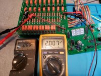
In the test illustrated below. I have placed 2V DC between the Left + input and ground as seen on the Fluke 179 meter. The volume is cranked up to 255 and I should be getting around 2V from the left + output and ground. What we see on my Fluke 73 is 0V. This is true throughout the volume range.
I also tested the other three boards with the same results. The switching works but the volume doesn't. On one board I reconnected the cut traces and tried to use it as a passive preamp with no success either.
Got any ideas where the problem might be?
Regards,
Roy
I seem to be having problems getting output from the volume control. I have cut the traces and placed short bare test wires in the switching out and volume in IO holes. Switching works great on all three analog boards but I am not getting any output when I try to put 2V DC through the volume inputs.
In the test illustrated below. I have placed 2V DC between the Left + input and ground as seen on the Fluke 179 meter. The volume is cranked up to 255 and I should be getting around 2V from the left + output and ground. What we see on my Fluke 73 is 0V. This is true throughout the volume range.
I also tested the other three boards with the same results. The switching works but the volume doesn't. On one board I reconnected the cut traces and tried to use it as a passive preamp with no success either.
Got any ideas where the problem might be?
Regards,
Roy
Attachments
I think one of the plausible cause of the pop noise, as member Neutrality speculated, could be the relays not cutting out sufficiently quickly.
"Lets say 00000000 is maximum attenuation and 11111111 is no attenuation.
What happens if you are at 01111111 and you turn up the volume by 1 step?" asked Neutrality
In this case if the MSB relay makes contact slightly sooner than the other relays break their contact, in a short moment the volume will be at 11111111, creating a big spike, until the lower bit relays do break contact.
Similarly, full volume 11111111 can happen when going from 10000000 one step down to 01111111. Same spike, but lower amplitude can also happen going at lower volumes, such as 0111 to 1000, and so on.
Well, how could a relay turn on sooner than other relays turn off when all the coil control transistors switch at the same exact moment?
The free-wheeling diodes that sit by every relay coil may be the culprit of slow contact release.
These diodes serve protecting the coil driving transistors from the coil's EMF back kick, by clamping the collector voltage to VCC (5V) at the moment the transistor turns off. Yet in so doing, the coil current gets to go on for a short moment even after the transistor turns off. As a result, the magnetic field that holds the contact gets go on holding the contact for a short moment, instead of instantly collapses releasing the contact.
If this mechanism sounds plausible and worth pursue, perhaps temporarily remove the protecting diodes, and replace the driving transistors with high voltage ones, 2N5551/MMBT5551 coming to mind, just to experiment.
Just a thought. I did not go through the entire thread. If I was repeating something/someone, my apologies.
As I said earlier in post 365, I have observed that the cause of the pop noise is indeed the quick and short duration to high volume intensity change. That is why my solution is efficient to reduce significantly this issue because the MSB relays switches one after the other. I have done it with hardware RC delay on the the relay driver command but could be done at the firmware if you have access to modify the code. I had tried first removing the diode across the relay coil as an experiment but it was not resolving the issue.
If you have access to the firmware code to create and adjust these delays to relays command than it should also work.
Of course the best solution is to use a zero crossing detector at input signal to switch the relays so high volume of no signal is still no signal 😉
Fab
If you have access to the firmware code to create and adjust these delays to relays command than it should also work.
Of course the best solution is to use a zero crossing detector at input signal to switch the relays so high volume of no signal is still no signal 😉
Fab
Last edited:
Hi Roy,
Do you hear the relays clicking on and off as you turn the rotary encoder and if you put a voltmeter across the diode at the relay you should see the voltage go from .2 to 4.8 or so when a relay is on. And be sure the mute isn't on. 🙂
If just one relay is on you should see something.
Hey Nattawa and Fab,
Something to think about though not sure how to make a relay coil discharge faster, again something to think about. Funny I didn't see this issue on my original design which the digitally weighted volume control. It should have had the same problem but it was absolutely quiet, no pops at all. I will also have to look at the chips driving the relay transistors again.
Thanks,
John
Hello John
Normally digital cmos switches change state faster than relays so it may be not or less audible. However, if you look at digital switch based volume control IC they mentioned a zero crossing detector to get best switching results….
See extract of PGA2311 datasheet :
« 7.3.4 Zero-Crossing Detection
The PGA2311 includes a zero-crossing detection function for noise-free level transitions. The concept is to change gain settings on a zero-crossing of the input signal, thus minimizing audible glitches. This function is enabled or disabled using the ZCEN input (pin 1). When ZCEN is LOW, zero-crossing detection is disabled. When ZCEN is HIGH, zero-crossing detection is enabled.
The zero-crossing detection takes effect with a change in gain setting for a corresponding channel. The new gain setting is not implemented until either a positive slope zero crossing is detected, or a time-out period of 16 ms has elapsed. In the case of a time-out, the new gain setting takes effect with no attempt to minimize audible artifacts.«
Fab
Last edited:
John,
I am getting results on the volume problem. I started by checking the diodes on the switching relays that I knew worked. Sure enough, I was getting close to five volts on the diodes of the input relays that were indicated on the display as active.
I then checked the values of 100, 101 and 102 on J1, the digital board input saw the unique set of high (approximately 5V) values for each input setting. I found the same true for the mute pin. This left D1 - D9 for controlling the volume relays. After testing which pins went high (approximately 5V) as the volume was turned up, I found it to follow a code and appeared to be operating properly.
I then checked the volume diodes and found that they only reached 1.2V rather than 5V when they tried to go high, probably not enough to trip the relays. The obvious question is the relay driving transistors. The BOM called for 2N3904s but they were not in stock. I ended up substituting BC549Bs at your suggestion. Could they be causing the problem and is there a viable option for that transistor?
Regards,
Roy
I am not keen on passing the audio signal through a CMOS switch, they add a harmonic distortion component to the signal, not to mention they would increase the cost over a relay. I am looking at the relay coil voltage at the moment. I used 5v coil voltage on the first design as they were available but when they weren't available on the new design I used a 4.5v coil which is in range of the voltage to switch on and off but not sure if there is a switching speed difference. Something to test.
Hi Roy,
1.2 volts at the relay isn't enough voltage to switch on the relay. Sounds like the transistor isn't turning on hard enough to pass the full voltage. I haven't had an issue using the BC549 as a switch for LEDs and other devices. Testing to find out has some risk, I think the chip can drive the transistor base directly without pulling to much current from the chip. You can try bypassing one of the resistors to the transistor base, just do one for testing, a jumper wire across the resistor would do it. If that works then we know it is base current. Safest option would be to put in the 2N3904, looks like Mouser has 200k of them in stock now.
Substituting some parts can be tricky, one batch of transistor works and the next batch doesn't. In the digital realm I have always been able to substitute a 74ACT part for a 74LS part but testing for timing changes is always required.
Last edited:
John,
I am getting results on the volume problem. I started by checking the diodes on the switching relays that I knew worked. Sure enough, I was getting close to five volts on the diodes of the input relays that were indicated on the display as active.
I then checked the values of 100, 101 and 102 on J1, the digital board input saw the unique set of high (approximately 5V) values for each input setting. I found the same true for the mute pin. This left D1 - D9 for controlling the volume relays. After testing which pins went high (approximately 5V) as the volume was turned up, I found it to follow a code and appeared to be operating properly.
I then checked the volume diodes and found that they only reached 1.2V rather than 5V when they tried to go high, probably not enough to trip the relays. The obvious question is the relay driving transistors. The BOM called for 2N3904s but they were not in stock. I ended up substituting BC549Bs at your suggestion. Could they be causing the problem and is there a viable option for that transistor?
Regards,
Roy
2n3904 may has a different pin out from that of bc54X...ebc vs cbe.
The base drive current of the design was generous at about 2mA and a transistor having half decent beta would have no problems saturate at 56ma Ic. Hfe>=30 is all it needs. But if reverse e-c, you get beta = 10 if you're lucky.
Hello John,
I went through the datasheet of the relay EC2-NU. It has the operate time at 2mS and release time at 1mS, suggesting a break-b4-make with a 1mS margin in your design. I think that should render a secure and smooth operation. What I had thought to be a probable cause for the popping sound, from making-b4-breaking operation due to the clamping diode, should not be the concern.
I have an unrelated question, John, that the schematic diagrams attached with post 280 seem to suggest the order of MSB-LSB on the relay control bus is flipped between J5 on the digital board and J1 on the analog board, if these two connectors are to be wired up by their pin numbers straight up. Is that the way it's supposed to be or did I read the diagrams the wrong way?
nattawa,
You we correct with your hunch of an ebc vs cbe problem. I should have checked the pinouts myself before I made the substitution.
Regards,
Roy
You we correct with your hunch of an ebc vs cbe problem. I should have checked the pinouts myself before I made the substitution.
Regards,
Roy
Ah yes, been a long time but now I remember that I had to install the BC549 facing backwards to work. Pull the part turn it around and put in, it should work.
Now, I have been thinking about the first design didn't pop and the new design sometimes pops, on the new design I used 4.5v relays on all and 5v relays on the previous design. I will pull some of the input selection 5v relays from the old board and swap with the 4.5v resistor relays on the new design to see what happens. The 4.5v relay will work fine in the input selection section. This is just to see what will happen.
Probably no difference but can't hurt to try.
On the wiring of MSB vs LSB from board to board let me look at the schematic again and reply in the next post.
- Home
- Source & Line
- Analog Line Level
- Preamp Control - Volume, input, mute, remote