Currents too low...
Ever since I built this buffer I have noticed that the KSA1381's heatsinks only get barely warm.
So after seeing Felipe's currents posted, I decided to measure one channel. Sure enough the currents seem to be lower than what's in Calvin's simulation(s).
The measurements are posted below. Transistors and resistors are exactly the same as what's in the schematic, except I'm using KSA1381 in place of 2SA1381. Power supply is +- 18V.
Can someone please tell me what's wrong and how I can get the currents up?
Thanks...
Attachments

Last edited:
Ever since I built this buffer I have noticed that the KSA1381's heatsinks only get barely warm.
So after seeing Felipe's currents posted, I decided to measure one channel. Sure enough the currents seem to be lower than what's in Calvin's simulation(s).
The measurements are posted below. Transistors and resistors are exactly the same as what's in the schematic, except I'm using KSA1381 in place of 2SA1381. Power supply is +- 18V.
Can someone please tell me what's wrong and how I can get the currents up?
Thanks...
What is the Idss of your master JFETs?
Could you check the negative rail with 180 ohms dummy load in place of the buffer to check if the PSU can give enough power?
Have you checked proper KSA1381 orientation?
Have you checked proper KSA1381 orientation?
Last edited:
What is the Idss of your master JFETs?
Approximately 4mA.
I have extra 5102's that measure anywhere from 4mA to 11mA.
Last edited:
Could you check the negative rail with 180 ohms dummy load in place of the buffer to check if the PSU can give enough power?
Have you checked proper KSA1381 orientation?
Felipe, the power supply should certainly be large enough because I was using it to power a Pass BA-3 before connecting it to this buffer.
Power supply is a LM317/337 and a large toroidal transformer.
Voltage is rock steady with this buffer at 18V and the BA-3 at 24V.
I'm assuming the 1381's orientations are correct since the PCB has been used in the past without issues.
I mounted the transistors to the heat sinks first and then soldered them to the board. I'll double check that I didn't accidentally turn any of them backwards before mounting them to the heat sinks.
This is Rudi's example, but mine looks the same.
Attachments
Master JFETs 4mA is too low, KSA1381 aren't working. Mine LSK389 Idss 7.26 mA. Calvin simuled the schematic I use with LSK389 Idss 8.3mA.
Last edited:
Master JFETs 4mA is too low, KSA1381 aren't working. Mine LSK389 Idss 7.26 mA. Calvin simuled the schematic I use with LSK389 Idss 8.3mA.
Thank you Felipe. Your readings look much closer to simulated than mine...that's for sure.
I didn't think the 1381's were working like they should by them being only slightly warm.
I'll replace the 5102's with a pair that have higher Idss.
OK, so if your devices are 7.26mA and the simulation uses 8.3mA, do you or anyone else know what the minimum and maximum Idss values are that can be used in the circuit without changes?

Approximately 4mA.
I stand corrected...their Idss is 4.9mA.
I couldn't remember for sure since I soldered them in several days ago.
Hi,
@ammel68. Nothing is wrong with Your Buffer.
In fact everything looks perfectly well.
Just the current values are low, due to the low Idss of the Master JFETs.
Neglecting the tiny base currents into the bipolars, the current through the JFETs is also the current through R101+R102, resp. R108A||R108B.
The voltage drop over these resistors equals the base-emitter voltage plus the emitter resistor voltage of the bipolars.
Above ~680mV the bipolars open up.
If the voltage at the base is higher, the additional voltage drops over the emitter resistor, causing the current (Vb-Vbe)/R to flow.
In case of #605 the Vbe is Vb-Vr (747mV-63mV), hence Vbe is 684mV.
The emitter current then is 63mV/6R8 = 9.26mA.
The Resistor R106 (resp. R111) carries the combined currents of the JFETs and the bioolar (added the neglected base current).
To increase the current through R106 (R111) there are several possibilities.
1- decrease the emitter resistors R105 and R107. 3R9 will roughly double the current. Tolerance sensitivity increases though with decreasing resistor values.
2- increasing R101+R102 (resp. R108A||R108B) to increase the base voltage of the bipolars. More effort and reduced Bandwidth. The base resistors of a CFP should be kept small.
3- change the Master JFETs to types with higher Idss. 6mA-10mA should work fine. Watch heat power dissipation of the bipolars. Cooling fins of the bipolars should get no hotter than 60°C.
Lower than 6mA and higher than 10mA would rather ask for a different dimensioning of several parts.
jauu
Calvin
Last edited:
Calvin: I need your advice, please!
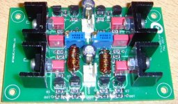
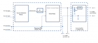
I have layouted, built and programmed a passive PRE-Amplifier that is being based upon "LDR-attenuation" (which is kind of similar to the technique that George_HiFi uses - see image1).
My German DIY-mate HANS judges the LDR attenuation as a very, very well sounding solution!
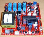
But he wants more! More drive, dynamics, more emphasis, and this is the reason, why I have "married my LDR - attenuation solution" to your buffer (Image2).
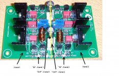
The LDR-based PRE-amplifier works very well with the outputs of the LDR-attenuation (see picture 3).
But: as soon as I connect your buffer to my VC-PRE and connect it to the used SYMASYM - amplifier and speakers: it produces an awful, persistently lasting hum, and I am afraid about the lifetime of my speakers.
(I am aware of the time it takes to settle your buffer to a thermally stable working-point and took the needed precautions.)
I am using your buffer as "line-buffer"!
- I am able to adjust the DC-voltage between IN+ and IN- to a value which is very near 0mV!
- I see a nearly "perfect sine- and square-wave" on my oscilloscope
Do these two observations listed above guarantee that your buffer is working perfectly, but I am having some "mechanical" issue?
Please: tell me.
Best regards - Rudi
I have layouted, built and programmed a passive PRE-Amplifier that is being based upon "LDR-attenuation" (which is kind of similar to the technique that George_HiFi uses - see image1).
My German DIY-mate HANS judges the LDR attenuation as a very, very well sounding solution!
But he wants more! More drive, dynamics, more emphasis, and this is the reason, why I have "married my LDR - attenuation solution" to your buffer (Image2).
The LDR-based PRE-amplifier works very well with the outputs of the LDR-attenuation (see picture 3).
But: as soon as I connect your buffer to my VC-PRE and connect it to the used SYMASYM - amplifier and speakers: it produces an awful, persistently lasting hum, and I am afraid about the lifetime of my speakers.
(I am aware of the time it takes to settle your buffer to a thermally stable working-point and took the needed precautions.)
I am using your buffer as "line-buffer"!
- I am able to adjust the DC-voltage between IN+ and IN- to a value which is very near 0mV!
- I see a nearly "perfect sine- and square-wave" on my oscilloscope
Do these two observations listed above guarantee that your buffer is working perfectly, but I am having some "mechanical" issue?
Please: tell me.
Best regards - Rudi
Attachments
Last edited:
Hi Rudi,
Try this:
Disconnect the passive pre from the buffer and connect the buffer to the power amp in two options:
1. The input of the buffer open (with only 100K resistor at the input of each channel, as in the schematic).
2. The input of the buffer shorted.
See what will happen to the hum.
Try this:
Disconnect the passive pre from the buffer and connect the buffer to the power amp in two options:
1. The input of the buffer open (with only 100K resistor at the input of each channel, as in the schematic).
2. The input of the buffer shorted.
See what will happen to the hum.
@ammel68. Nothing is wrong with Your Buffer.
In fact everything looks perfectly well.
Just the current values are low, due to the low Idss of the Master JFETs.
3- change the Master JFETs to types with higher Idss. 6mA-10mA should work fine. Watch heat power dissipation of the bipolars. Cooling fins of the bipolars should get no hotter than 60°C.
Lower than 6mA and higher than 10mA would rather ask for a different dimensioning of several parts.
Calvin, thank you for your reply and help!
I actually used the buffer with the 4.9mA Idss JFET's for several days and thought the sound was very good...surprisingly good in fact.
Only when Felipe posted his measurements, did I get curious about the same measurements of my example.
Anyway, your #3 suggestion above seemed like the logical choice, so I found a nice closely matched pair of 8.27mA JFET's and soldered them in one channel. Sure enough, within a couple of minutes of powering it up, the heatsinks were noticeably warmer than the other channel which still had the lower Idss devices soldered in place.
Unfortunately, probably about 1/3 of my batch of 5102's measure between 4-5.9mA or over 10mA. I'm not sure what I can do with these devices that fall outside the preferred range of 6-10mA.🙁
Thank you again...
@ammel68
What's the inductor value?
I believe its value is 10uH.
The assembly guide suggested wrapping about 10 turns of solid wire around a small screwdriver.
- Home
- Source & Line
- Analog Line Level
- Preamp-Buffers - simple idea