To call the Calvin low transparency is strong poison.
Even the standart buffer in the Paradise is better then any B1 incarnations i know of in my humble opinion.
Countless Paradise builders see the Calvin as a worthwhile improvements.
More slamm, more human, more musical.
I could only imagine that there is something wrong with this particular build, oszillation and such .....
I didn't say anything about the "Calvin" having low transparency. I've never even heard a "Calvin" buffer before.
I was referring to a simple buffer that used 2 FET's that I think Mr. Marsh posted some time ago. Go back and reread posts 283-286.
Next time, how about making sure you're referring to the correct circuit before accusing me of "strong poison"...whatever that is.🙂
Hi,
calm little Joe, calm 😀
Ammel talked about a simpler complementary JFET follower with a resistor modification as linked in #283.
jauu
Calvin
Hi Calvin,
Is there a link to the schematic for the buffer in the Paradise that Joachim is referring to?
Also, what is the Paradise?
Thanks...
Edit--I just found the Paradise phono preamp and a group buy thread for the buffer PCB's. Since the last post was back in July, is it safe to assume the Calvin buffer PCB's are no more?
http://www.diyaudio.com/forums/group-buys/239776-calvin-buffer-paradise.html
Last edited:
Hi,
maybe someone as a couple of PCBs left.
The Paradise Version is designed with throughhole parts only.
You may build it on a plain Testboard hardwired.
User Curryman made an all SMD design for 2-layer PCBs.
I made an all smd 2-layer design, that may be converted to and used with single layer pcbs as there's only one trace and a grounded shield on the bottom layer.
So You could easily etch PCBs Your own.
jauu
Calvin
Did I understand the last post correctly?
I have quite a couple of my own layout of Calvin's buffer, using SMD-resistors, left.
Since my eyes have grown old since I did the SMD-layout, I am no more able to solder the PCBs and will happily sell you Calvin's buffer for 5€ per PCB(shipping included!).
Best regards - Rudi_Ratlos
I have quite a couple of my own layout of Calvin's buffer, using SMD-resistors, left.
Since my eyes have grown old since I did the SMD-layout, I am no more able to solder the PCBs and will happily sell you Calvin's buffer for 5€ per PCB(shipping included!).
Best regards - Rudi_Ratlos
Attachments
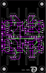
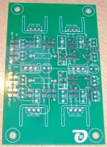
I also have a few boards left (all SMD, 50 x 50 mm, quite similar to board shown in post #250). Just send me a PM if you're interested.
kind regards, Daniel
kind regards, Daniel
I'm not a big fan of SMD, but I've had pretty good luck soldering 1206 devices.
Will these boards accept 1206 devices or are they designed for smaller devices?
Too bad someone hasn't come up with a dual through-hole board. Perhaps that's something I may try to design in the future.
I need to hear one of these buffers first, though.
I see the 2SA1381's are obsolete. There are some on eBay, but who knows whether they are fake or not.
What input and output devices, that aren't obsolete, are recommended?
Ammel68: here is, where Calvin published the Builder's guide of his buffer.
https://docs.google.com/file/d/0B0CkKjTuzoyOMHd4WHFiLWlCczg/edit?pli=1
On the bottom of page 3 you will find replacements for the SA1381.
Best regards - Rudi
https://docs.google.com/file/d/0B0CkKjTuzoyOMHd4WHFiLWlCczg/edit?pli=1
On the bottom of page 3 you will find replacements for the SA1381.
Best regards - Rudi
Ammel68: here is, where Calvin published the Builder's guide of his buffer.
https://docs.google.com/file/d/0B0CkKjTuzoyOMHd4WHFiLWlCczg/edit?pli=1
On the bottom of page 3 you will find replacements for the SA1381.
Best regards - Rudi
On top of that, KSA1381 is a direct replacement for 2SA1381 and is available at Mouser.
I'm not a big fan of SMD, but I've had pretty good luck soldering 1206 devices.
Will these boards accept 1206 devices or are they designed for smaller devices?
It's mostly 0805 or even 0603 😛 I'm sorry. Once you're used to soldering SMD it's hard to go back 😉
kind regards, Daniel
Once you're used to soldering SMD it's hard to go back 😉
I don't know about that. I think most people, especially if given a choice, will always prefer through-hole devices.
If you happen to drop a through-hole component, at least you can usually find it easily...not so with "chip" components.
Anyway, thank you for your reply about the boards.
Did I understand the last post correctly?
I have quite a couple of my own layout of Calvin's buffer, using SMD-resistors, left.
Since my eyes have grown old since I did the SMD-layout, I am no more able to solder the PCBs and will happily sell you Calvin's buffer for 5€ per PCB(shipping included!).
Best regards - Rudi_Ratlos
Rudi, how about the boards you have? Are they also designed for the small 0805 resistors, or something larger?
Thanks...
On top of that, KSA1381 is a direct replacement for 2SA1381 and is available at Mouser.
Thank you for the tip, Joshua!
Mouser is my preferred choice for components, so that's good to know.
Calvin and all others,
On the Hybrid Compound Super Buffer and on the Calvin Buffer for Paradise the NJFETs being cascoded are of relatively low IDSS.
I have very many 2SK170s, of V, BL and GR grades. Is there any benefit (subjective or measured) in using higher IDSS ones?
Also, what's the impact of selecting certain idle current for the BJTs?
Hi,
Basically You just need enough current through the JFETs to steer the BJT open under all circumstances.
Depending on the maximum output load current and the current gain of the BJT the required JFET current can be estimated.
As a rule of thumb, choose the idle current 5-10times the maximum load current if THD shall remain negligible till clipping.
In our case even 1mA JFET current should suffice.
But JFETs sound seems to improve when they are biased ´hot´.
Seems that for SK170 ~4mA is a good bias point.
That is also low enough that the heat power losses of the Master JFET and Slave JFET stay within safe limits.
By the choice of the Source resistor, the Drain resistor and the emitter resitor You can define overall current as well as current distribution among the JFET and bipolar branch.
The Source resistor defines the overall current and Drain and emitter resistors define the distribution of the split currents.
If You choose a higher Idss JFET as Master, then the overall current and the current through the Master will increase.
If You now want to reduce the overall current to the original value You need to increase the source resistor.
If the higher overall current is ok, but You want to decrease the current through the JFET, then increase the emitter resistor or decrease the drain resistor.
The latter beeing preferable as the drain resistor influences on the bandwidth of the transistor compound.
I´ve done successfull simulations with the higher Idss BF862s and iIrc someone actually build the buffer successfully with BF862s.
So I´won´t worry about the higher grade SK170s.
Just see that the Vgs of the cascoding JFET is still high enough, ~4V, to provide for the Master JFET sufficient Vds.
jauu
Calvin
Last edited:
Thanks Calvin for the good explanations 🙂
I've succesfully used BF862 with IDSS arround 15-20mA cascoded with SST4391.
kind regards, Daniel
I've succesfully used BF862 with IDSS arround 15-20mA cascoded with SST4391.
kind regards, Daniel
Hi Calvin,
Thank you very much for your detailed and comprehensive explanation.
I have enough 2SK170s of all grades to choose any Idss for matched pairs, or matched quads. It looks like choosing Idss of about 8-8.5mA is a good choice.
As for your comment about the higher JFET needing Vgs ~4V, on the Calvin Buffer for Paradise, J107 is used, however it seems that J105 would be a better choice. Is that correct?
- Home
- Source & Line
- Analog Line Level
- Preamp-Buffers - simple idea