Use mApk when describing a peak current.
Save mAac for AC levels, mAdc for a constant DC current and mApp/mVpp for reading off a scope.
This avoids ambiguity and confusion especially among beginners that are struggling to grasp the topic.
Save mAac for AC levels, mAdc for a constant DC current and mApp/mVpp for reading off a scope.
This avoids ambiguity and confusion especially among beginners that are struggling to grasp the topic.
Gurevise,
you don't have to use 50r to terminate your 50ohm coax.
You could use separate audio frequency loading from VHF frequency loading.
say you want a 1k as your audio load.
Then add a 50r + 10nF cap as the cable termination, F-3dB ~ 300kHz.
All the fast signals >200kHz, see the 50r as the load, all the audio see the 1k as the load.
The buffer produces insignificant VHF and thus never passes significant VHF current to the 50r+10nF.
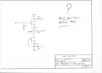
Here is an even easier, simple circuit that has only 2 jFET's and 3 resistors:
Using +22 and -22 vdc supplies, 2H and 3h and beyond are all <-120dB. R4 nulls the THD to almost nothing without cascoding.
Thx-RNMarsh
View attachment 360321
Hi Richard,
Two questions:
1. Will it work as good, or nearly as good, with 2SK170 / 2SJ74 pair?
2. Would decreasing the positive voltage supply, compared to the negative voltage supply, have the same effect, or nearly the same effect?
Just built the Marsh circuit above. It may have low distortion, but I measure 50mV offset at the outputs with a 19 volt supply.
Looks as though the circuit needs a cap or some type of servo to reduce the DC.
Looks as though the circuit needs a cap or some type of servo to reduce the DC.
Ammel,
are you referring to sch in post283?
That shows 250r in the source leads of the jFETs.
A trimmer just like we see in many Pass builds solves the output offset, if the jFETs are not exactly matched.
are you referring to sch in post283?
That shows 250r in the source leads of the jFETs.
A trimmer just like we see in many Pass builds solves the output offset, if the jFETs are not exactly matched.
Yes, the circuit in post #283.
I'm sure the JFET's aren't anywhere near matched as I just picked up whatever I could find on the Bay.
Mouser still has some 5458's, but no-go on the 5461's.
So I need to substitute a trimmer for the 250 ohm resistors?
If I use a trimmer, how do I connect its 3 leads compared to the resistor it replaces?
Thanks...
No, look up the Pass circuits (there are a few) that use source resistors in the Nch and Pch jFETs. Some have a trimmer added.
ADD a trimmer.
ADD a trimmer.
Yes, the circuit in post #283.
I'm sure the JFET's aren't anywhere near matched as I just picked up whatever I could find on the Bay.
Mouser still has some 5458's, but no-go on the 5461's.
For very low DC at the output, the JFETs must be matched for Idss.
So I need to substitute a trimmer for the 250 ohm resistors?
Either use a trimmer permanently, or, better still, use a trimmer to define the exact resistance value and then replace it with a fixed resistor.
If I use a trimmer, how do I connect its 3 leads compared to the resistor it replaces?
You connect the center tap to one of the ends and solder both ends in the place of the resistor.
Thanks for the replies. I was able to get the offset down much lower.
It could just be me, but I found the sound quality of this very simple circuit disappointing...not transparent at all, but rather veiled.
Oh well, at least it didn't cost much or take much time to assemble.🙂
My search for a good, easy to build buffer continues.
It could just be me, but I found the sound quality of this very simple circuit disappointing...not transparent at all, but rather veiled.
Oh well, at least it didn't cost much or take much time to assemble.🙂
My search for a good, easy to build buffer continues.
Hi,
the JFET pair chosen is probabely one of the very few complementary pairs still on market.
Apart from that, I wonder why one would choose them.
Low Idss, high Vgs, low gm, high output impedance, high voltage noise.
Not the specs of first choice for me.
That is, why I chose SE circuitry instead of complemtary.
Btw. these simple circuits react quite sensitive to the amount and quality of the caps at the supply lines.
jauu
Calvin
Last edited:
Calvin, do you have any links to buffers that you've tried and can recommend?
I would prefer something that I can put a volume pot in front of.
Thanks...
I would prefer something that I can put a volume pot in front of.
Thanks...
MUTE-Handling
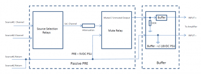
Gentlemen, I am having a question regarding my own PRE-Amplifier's design on how to handle MUTE.
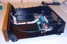
My design (2nd image, showing you a rough image) uses relays to select the chosen music-source.
(Image#2 is only showing the source-selection of 2 sources.)
The PRE uses a very ripple-free +5VDC PSU.
The selected music-source-signal is then attenuated by a schematic, which is based on a digitally controlled LDR solution.
The attenuated signal along with its return signal is then fed to a MUTE relay.
The PRE is followed by a buffer, having a separate +/-18VDC PSU.
As long as I do not press the MUTE switch, everything works fine.
But when I press the MUTE-switch: I hear a hum.
Muting an amplifier should be done by shorting the INPUT+ and INPUT- signals to the amplifier.
But in my case: INPUT- is connected to the BUFFER's GND and INPUT+ is connected to the BUFFER's GND via a 100 KOhm resistor .
Is this the reason, why I am hearing some hum?
How should I do the connections in my PRE?
Best regards - Rudi_Ratlos
Gentlemen, I am having a question regarding my own PRE-Amplifier's design on how to handle MUTE.
My design (2nd image, showing you a rough image) uses relays to select the chosen music-source.
(Image#2 is only showing the source-selection of 2 sources.)
The PRE uses a very ripple-free +5VDC PSU.
The selected music-source-signal is then attenuated by a schematic, which is based on a digitally controlled LDR solution.
The attenuated signal along with its return signal is then fed to a MUTE relay.
The PRE is followed by a buffer, having a separate +/-18VDC PSU.
As long as I do not press the MUTE switch, everything works fine.
But when I press the MUTE-switch: I hear a hum.
Muting an amplifier should be done by shorting the INPUT+ and INPUT- signals to the amplifier.
But in my case: INPUT- is connected to the BUFFER's GND and INPUT+ is connected to the BUFFER's GND via a 100 KOhm resistor .
Is this the reason, why I am hearing some hum?
How should I do the connections in my PRE?
Best regards - Rudi_Ratlos
Attachments
Last edited:
And you are perfectly certain that you have not accidentally wired up the relay so that instead of shorting the signal to ground, it just interrupts it? You may want to verify that. With a 100k input hanging in the air, you easily catch a hum.
Otherwise it would have to be some sort of grounding issue that's not obvious from your block diagram.
Otherwise it would have to be some sort of grounding issue that's not obvious from your block diagram.
I have a 20 years old tube preamp, which has a tape out buffer designed by John Curl.
Feeding this buffer from IVC (Inductive Volume Control) is the most transparent 'preamp' I ever heard.
Do you know of any reliable sources for the 2SK389?
I see a lot for sale on eBay from Asian sellers, but have no idea if they would be fake, or not.
For very low DC at the output, the JFETs must be matched for Idss.
The load must not be too low Z or distortion will rise; something like >50K is good.
I thought the 2SK389 dual device was no longer made for quite awhile now.
Thx-RNMarsh
Last edited:
Hi,
@ammel
This thread is about good buffers. Just choose Your poison 😉
The Calvin Buffer in its different incarnations has proven its suitability and qualities, not the least in dozens or maybe even hundreds of Paradise Phonos and as Standalones.
The CFP2 is very similar, basically repacing the cascoding JFET by a bipolar.
If higher impedance loads are used, the simpler Hybrid CFP (Calvin wo. cascoding JFETs) will suffice.
Going bipolar the ever so popular Diamond structure comes to mind.
For higher load impedances the Keantoken Buffer seems a good choice.
As for the SK389s, the possibly only reliable source are the new Linear Sytems LSK389 sourced from official distributors.
Original Toshibas are obsolete for some years by now.
Chances are very high to purchase Fakes
jauu
Calvin
To call the Calvin low transparency is strong poison.
Even the standart buffer in the Paradise is better then any B1 incarnations i know of in my humble opinion.
Countless Paradise builders see the Calvin as a worthwhile improvements.
More slamm, more human, more musical.
I could only imagine that there is something wrong with this particular build, oszillation and such .....
Hi,
calm little Joe, calm 😀
Ammel talked about a simpler complementary JFET follower with a resistor modification as linked in #283.
jauu
Calvin
calm little Joe, calm 😀
Ammel talked about a simpler complementary JFET follower with a resistor modification as linked in #283.
jauu
Calvin
- Home
- Source & Line
- Analog Line Level
- Preamp-Buffers - simple idea