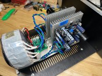
I used DUELUND 12 gauge cast jacket. I had it available and I like it.
The four 10mF caps are on a perf board with the leads in the middle which is likely not optimum but that was the best way to integrate. I can always change it if told it should be linear. I would change it.
The caps are placed so the the leads are available from the bottom (the tops are on placed on a piece of wood) which allows a short path to R25 in my installation.
From there to the stub of the snap in on tombo's board.
I could not take a photo that would show it any better than my explanation.

19V is required for a Corei3 based audio PC. So the load is almost constant.Power supply requires only a fraction of volt higher voltage at input to operate at full performance. However, in practice mains voltage variation and ripple at the first reservoir capacitor lead to 1 – 1.5 V required difference.
How much voltage will be available after rectification depends on transformer properties and load. With very light or no load, there will be about 1.39 x AC voltage. Depending on standard transformer loading, that would drop to 1.2 – 1.27 x AC voltage. So it depends on specific use case.
In general, 22V AC is too much and 17 – 18V could be enough. For what purpose would you like to use this supply and what load current is expected (constant or variable)?
Current is a good question. W2K19 is running in core mode, so I do not expect big current peaks. LT 1083 is sufficient.
So the constant load maybe is not so constant. It is better to check instead of assumption.
Anyway, it seems you could get away with an overdimensioned (current) 18V transformer.
Anyway, it seems you could get away with an overdimensioned (current) 18V transformer.
Using AWG 15 – 14 (1.6 – 2 square mm cross section), any length required inside amplifier’s case is not too long for the proper performance. We should keep length at the possible minimum to minimize radiated 100/120 Hz noise. Reservoir capacitors are charged with short high current pulses and that produces strong EM fields. By twisting two wires together, most of two opposing EM fields cancel out, but enough remains.Twisted, heavy gauge wire as short as possible would be my approach to connect off-board caps. But, what would be too long for "as short as possible"?
Then 17V AC would be about right. 18V AC is more than required but could be used if taking care for good power MOSFET cooling with external heatsink.19V is required for a Corei3 based audio PC. So the load is almost constant.
However, I don’t believe that there is anything to gain by replacing LT1083 supply for the PC with a better one. Digital circuits are noisy and, if I’m not mistaken, audio at that PC remains in the digital domain.
Fortunately I have sufficient external heatsink on side panel. it's a 16V 7A transformer. Without load it gives 18.2 V.Then 17V AC would be about right. 18V AC is more than required but could be used if taking care for good power MOSFET cooling with external heatsink.
However, I don’t believe that there is anything to gain by replacing LT1083 supply for the PC with a better one. Digital circuits are noisy and, if I’m not mistaken, audio at that PC remains in the digital domain.
Audio PC remains in the digital domain, but when I replaced the standard SMPS to the LT1083 linear supply, it was a big improvement. The same effect happened with ethernet switch. At least I will use it for my DAC. The parameters of your design impressed me, so I give it a try. 🙂
As jean-paul pointed out, that transformer will be fine.Fortunately I have sufficient external heatsink on side panel. it's a 16V 7A transformer. Without load it gives 18.2 V.
I don’t doubt improvement going from a SMPS to the LT1083 linear supply, but I suspect that it is hard to get further improvement on an audio PC. If you feel like it, report back results. It may help other members with the right decision.
For anyone in Germany, Holland, France or Belgium reluctant to order PCBs... I still have a few green ones normal quality for shipping costs.
 .
.
Thanks!
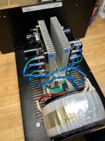
... yeah, I saw four secondaries and thought it must've been a custom order. Nice one from AnTek to give the option of 4 secondaries.
... yeah, I saw four secondaries and thought it must've been a custom order. Nice one from AnTek to give the option of 4 secondaries.
- Home
- Amplifiers
- Power Supplies
- Power Supply with Active Rectifier, RF Filter and Super-Regulator