Great foundation to build amplifiers upon. 😁Foundation is ready.

With that big transformer, there should be 34 - 35V before regulator part. Leaves headroom for some output voltage increase if required.The 25V secondaries deliver 26V5 output under load. Perfect for a little regulator dropout headroom.
Regulated output: +/-32V
Cooling is perfect so supply can also work with high current + considerable voltage drop.
Hello Tombo, I need some help. AC input is 18 V. DC is 24V at Q7 S. I have 0V at output. Green LED lights. At Q6 collector there is only 0.45 V, so there is no supply voltage for opamp. I checked Q6 and it's Ok.
First, check D1 orientation and measure between opamp pins 4 – 7 or C4 terminals for a short circuit.
D1 orientation is correct. With ohm meter it seems ok, but I replaced id. Temporarily I removed C4, there was no shortcut. Q6 E 24.7 V Q6 B 24V Q6 C 0.47V
OPA828 orientation is correct. There is 0.2V on R3, so B-E is closed.Is OPA828 soldered in orientation as shown at post #103?
Is there some 0.6V across R3?
Attachments
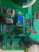
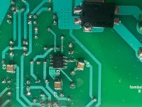
I would touch up on the soldering there, with flux added, it looks very sloppy and can easily be cause of your issues. Several pcb/trace damage but i'd not account it to the issue at hand. HF filter seems to have melted a bit, but not enough to eat trough as what can be seen.
Soldering doesn’t look very nice and there could be a problem at some point. But, we have to see first why there isn’t expected voltage at the base of Q7.There is 0.2V on R3, so B-E is closed.
Two biasing diodes (D4 + D5) should provide about -1.27V at the Q6 base, compared to the input rail voltage. Check D4 & D5 diodes. If green LED is lit, then biasing current is flowing but one 1N4148 diode may be burned or in short circuit.
Last edited:
There is only 0.4 V voltage drop on each diode (D4,D5) Q6 B-E is only 0.59VSoldering doesn’t look very nice and there could be a problem at some point. But, we have to see first why there isn’t expected voltage at the base of Q7.
Two biasing diodes (D4 + D5) should provide about -1.27V at the Q6 base, compared to the input rail voltage. Check D4 & D5 diodes. If green LED is lit, then biasing current is flowing but one 1N4148 diode may be burned or in short circuit.
OK. That raises a question if green LED is really lit or do you see some light reflection?
0.4V over each diode, means that only very small current (uA range) is flowing.
Possible cause is wrong orientation of the green LED. Check post #103.
0.4V over each diode, means that only very small current (uA range) is flowing.
Possible cause is wrong orientation of the green LED. Check post #103.
Measurements are weird. CCS diode D6 would pull close to 1.5 mA through D4 & D5 and very small current through BE junctions of Q6 & Q7. In that case, there should be > 0.6V over each D4/D5 diode. O.8 V is impossible if diodes are OK.
If one diode would be burned to short circuit, then it could be close to 0.8 V over one diode.
If one diode is burned to open circuit, then green LED would be still lit, as required current would be pulled through BE junctions of Q6/Q7. However, that would result with high output currents at Q6/Q7 collectors (>2V over R3/R5), but regulator would power up and work.
Did you actually measure each diode voltage for D4/D5 or just divided voltage at the Q6 base?
I measured again 0.4 V on each. I measured 0.8 V from V+ to Q6 B. I can replace them.Measurements are weird. CCS diode D6 would pull close to 1.5 mA through D4 & D5 and very small current through BE junctions of Q6 & Q7. In that case, there should be > 0.6V over each D4/D5 diode. O.8 V is impossible if diodes are OK.
If one diode would be burned to short circuit, then it could be close to 0.8 V over one diode.
If one diode is burned to open circuit, then green LED would be still lit, as required current would be pulled through BE junctions of Q6/Q7. However, that would result with high output currents at Q6/Q7 collectors (>2V over R3/R5), but regulator would power up and work.
Did you actually measure each diode voltage for D4/D5 or just divided voltage at the Q6 base?
Dzoli, besides improving skills (use a magnifying glass/lamp combination) please learn to first cut lead wires and then solder them. That way you will not put mechanical force on solder joints and the cut surface will also be soldered.
Get used to it and get reliability as reward.
Get used to it and get reliability as reward.
Last edited:
Replace D4 & D5.I can replace them.
If you have a spare, replace D6 as well if replacing D4 & D5 doesn’t bring any change.
@dzoli
measurements point to a problematic component in the D4, D5, D6, D7 string. Which one is hard to say as measured voltages are in contradiction with fact that green LED is lit. Anyway, replacing those parts one by one will reveal which one was the culprit.
What is voltage at green LED terminals? It should be about 1.9 V.
- Home
- Amplifiers
- Power Supplies
- Power Supply with Active Rectifier, RF Filter and Super-Regulator