Hi Hennady,
thanks a lot, never given up with me...
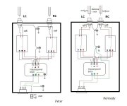
I will make the changes as shown in the right picture, only the RCA input i can't change to come nearer together. The rest..no problem. I have to drill only one hole for an other ground/earth connection.
Thanks
Peter
thanks a lot, never given up with me...
I will make the changes as shown in the right picture, only the RCA input i can't change to come nearer together. The rest..no problem. I have to drill only one hole for an other ground/earth connection.
Thanks
Peter
Peter, I started doing this option (on the right) because it showed a better construction of the stereo sound stage and less influence of interconnect wires, I saw a similar connection in some recommendations for concert amplifiers for the stage, there the GND was switchable, and at home it was turned off, so with I don't have a grounded outlet.Hi Hennady,
thanks a lot, never given up with me...
I will make the changes as shown in the right picture, only the RCA input i can't change to come nearer together. The rest..no problem. I have to drill only one hole for an other ground/earth connection.
Thanks
Peter
In any case, you can check this method of inclusion and compare with how you do it.
if 1 inch is a small size, then I make the distance along the RCA axis 30mm. Thus, the input terminals must be located nearby in the housing.
Hi Peter,
I'm very interested by this thread and your experience with LJM amps.
Do you have the schematic of the L20.5?
Thanks
Alain
I'm very interested by this thread and your experience with LJM amps.
Do you have the schematic of the L20.5?
Thanks
Alain
"I do not see any BE-discharge resistor at the output transistors to prevent cross-conduction. Very risky!" bucks bunnyAlso in the attachment is an already corrected version of both the formation of stability inside the amplifier and under a complex load, pay attention to the values of the Thiel circuit at the output of the circuit.
maybe you're looking in the wrong place? Show me where these resistors should be and what their value is, and we’ll think about it....I do not see...bucks bunny
Seen at: https://www.diyaudio.com/community/threads/l20-amp-use-only-two-njw0302g.199093/post-7584343
"Power BJTs require some means to force remove charge from the base when turned off. This is basic knowledge myriads of other people have explained in detail. And you will find these in class AB amps since the sixties when 2N3055 was the workhorse."
"Power BJTs require some means to force remove charge from the base when turned off. This is basic knowledge myriads of other people have explained in detail. And you will find these in class AB amps since the sixties when 2N3055 was the workhorse."
I see your option like this, see attachmentI will make the changes as shown in the right picture,
Attachments
Sorry, I advise you to read a little more carefully, because... These resistors are necessary when the driver stage also works synchronously with the output transistor, and no matter how vintage it is from the 60s. In the case of the Lokanti cascade, this resistor provides a floating bias, at which the driver stage is not completely turned off and does not require additional charging/discharging by resistor BE. This problem is important in the market version of LJM, where it is relevant.Seen at: https://www.diyaudio.com/community/threads/l20-amp-use-only-two-njw0302g.199093/post-7584343
"Power BJTs require some means to force remove charge from the base when turned off. This is basic knowledge myriads of other people have explained in detail. And you will find these in class AB amps since the sixties when 2N3055 was the workhorse."

@alain98
I am sorry, i have found only one schematic in the i-net. https://tonbandforum.de/showthread.php?tid=26889
I gont know if everything is right....
One thread about the L20.5 https://www.diyaudio.com/community/threads/l20-5-ap-sys-test-data-my-design.323965/page-2
in post 37 there is are pictures taken from the pcb.
Peter
Attachments
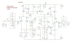
Regarding the improvement diagram "corretion2.jpg" that you suggested:Try to do it as in the attachment - and the slew rate will be higher and it will be easier for the amplifier to “breathe” at high frequencies.
Correction changes are highlighted in red.
1. Couldn't the Miller cap be lowered to 10pF (this would reduce the gain spike above 20KHz)?
2. Why are you placing a 100R below the 330 pF cap connected to the base of the Q24)?
3. On the gain control, changing from 330R to 1K will reduce distortion by significantly reducing the gain. Wouldn't a value of, say, 450R be a better compromise?
4. Why do you put an extra 22pF on the Q16's collector?
1. no, this will increase the unity gain frequency from 2 MHz to 6 MHz and degrade stability
2. this increases the stability margin by 26 degrees. The cutoff frequency of the input circuit is 285 kHz, and the input differential stage with Miller correction above 40 kHz no longer amplifies anything (high nonlinearity), so it only affects the stability margin.
3. The gain cannot be infinite, it depends on the supply voltage and the rated input voltage. With an input amplitude voltage of 2 Volts (1.4 V RMS) and a resistance of 330 Ohms, the gain will be 10k/330=30 times, i.e. 2*30=60 or +/-30 Volts, and the amplitude limitation at Supply Voltage +/-32 Volts will be +/-25 Volts, and the question immediately arises: why is there excessive sensitivity at the amplifier input? increase noise? Conclusion, if you want to leave 330 Ohms, then you need a supply voltage greater than +/- 45 Volts.
4. it stands at the input of the emitter follower of the output stage. limitation of the frequency spectrum above 10 MHz at the input of the emitter follower, which has 100% negative feedback on low-frequency power transistors. The spectrum should not exceed the frequency capabilities of power transistors - because of this, IM- distortion increases, i.e. dynamics worsen.
I just soldered the correction option 2, see attachment, on MX50 boards, I have a working model of this amplifier on this board. I adjusted the denominations R1 R2 R13 - marked in red. According to the model, the linearity of the input diff stage is +/-2 dB at a frequency of 20 Hz - 20 kHz, the gain of the input diff stage is Q1Q4 30dB, Q8 cascade gain 51dB, total gain of open loop 81dB Linear was also +/-2.5dB at the amplifier output.
Now I've assembled it and turned it on and enjoying the sound....
Capacitors C3 C5 WIMA, C2 C7 - ceramic NPO
I did this to make it clear that these are real working solutions for correction.
What we get as a result is that all cascades have only linear local feedback, the feedback is also linear, because resistor only, parasitic capacitances can be ignored.
Attachments
And that 1 transistor Q8 in the part of the voltage amplifier is better than two, as it was in the original? Why is that?
You need to ask LJM why he installed 1 transistor when Self even has 2 transistors in his book.And that 1 transistor Q8 in the part of the voltage amplifier is better than two, as it was in the original? Why is that?
This is a correction tweak for a finished MX50 board from AliExpress, where the frequency correction needs to be hung on the bottom side of the board, additionally cutting tracks and soldering a transistor with a common collector, a load resistor and an anti-overload resistor does not allow the installation density, you need to design a different board, especially since correction will require local 2-pole correction. Those. this is a more difficult path.
The project on the topic of LJM board L20SE is a dead end, this project is subject to complete rework due to nonsense in the form of shiklai in the diff stage and load resistors from a high point to the bus and the lack of discharge resistors in the power output transistors. There’s not even anything to discuss here - somehow it will work and that’s it...
The material and methods used to compare L20SE and MOD Hennady 2024 were:
1. Software NI MultiSIM 14.3
2. The power supply voltage (+/- 50V) and the gain (R15 470R) were adjusted to output the same 25.8 Vrms output (111 W)
3. The software was left runing for the same time (10 minutes)
The MOD Hennady 2024 multisim file is attached to this post.

1. Software NI MultiSIM 14.3
2. The power supply voltage (+/- 50V) and the gain (R15 470R) were adjusted to output the same 25.8 Vrms output (111 W)
3. The software was left runing for the same time (10 minutes)
The MOD Hennady 2024 multisim file is attached to this post.
Attachments
I agree with many things that Hennady has written and accordingly, I have made changes to the L20SE design:
1. I have reduced the value of the Miller capacitor C5 from 100pF to 47pF and it measures better (the bode plot looks better).
2. I have not been able to find any published principles applicable to this design for using an additional 100R resistor below the 330pF C1.
3. I have reduced the gain by changing R15 from 330R to 470R and it measures better.
4. I have not been able to find any published principles applicable to this design for using an extra 22pF on the Q10 collector.
Regarding frequency shaping by using low and high pass filters at the input and output of an amplifier, I belong to the old school of thinking that an amplifier should be just "a wire with gain".
In my particular case, the input of this amplifier comes from a good DAC with its almost perfect 20~20kHz and 2V output, so it seems to me that this is all the filtering I need for now.
Last edited:
Very poetic, if it weren’t so sad to read this. The input and output filters operate outside the 20-20 kHz frequency range of your best DAC. And according to your statement, the “gain wire” is an amplifier where there is a correction capacitor in the local feedback circuit, the capacity of which, in fact, taking into account this “gain wire” is thousands of picofarads, i.e. In your "old school" interpretation, the gain wire is a low-pass filter with frequency feedback that is corrected by deep negative feedback.Regarding frequency shaping by using low and high pass filters at the input and output of an amplifier, I belong to the old school of thinking that an amplifier should be just "a wire with gain".
Congratulations - this is super)))
Your DAC is not a “spherical horse in a vacuum” - and its signal is not transmitted to speaker systems by an effort of thought. To do this, an amplifier is designed from very nonlinear elements with a very high frequency dependence, and for all this to work efficiently, the unity gain frequency must be 100 times higher than 20 kHz... Why 100 times and not 50 times? you can find the answer by delving into your "old school", is all just...In my particular case, the input of this amplifier comes from a good DAC with its almost perfect 20~20kHz and 2V output, so it seems to me that this is all the filtering I need for now.
- Home
- Amplifiers
- Solid State
- Power Amplifier LJM L20SE