Hi,
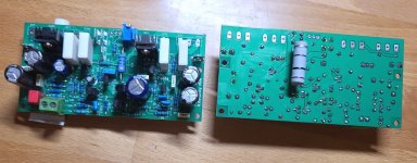
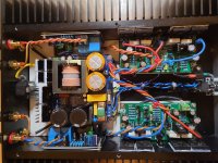
2 boards assembled. I have to test in the next days.
I am not lucky with this pcb's. The values are not quite right at the input or the capacitors. They are changed to the last mod on the newer pcb.
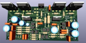
I have made another version to get more space for the emitter resistors and the drivers. Dont know if i have to use them...but finished.
Kind regards
Peter
2 boards assembled. I have to test in the next days.
I am not lucky with this pcb's. The values are not quite right at the input or the capacitors. They are changed to the last mod on the newer pcb.
I have made another version to get more space for the emitter resistors and the drivers. Dont know if i have to use them...but finished.
Kind regards
Peter
Attachments

Hello!
That big resistor can be soldered vertically from the face of the board so that it doesn’t have to be attached to the side of the tracks.
That big resistor can be soldered vertically from the face of the board so that it doesn’t have to be attached to the side of the tracks.
Hi Hennady,
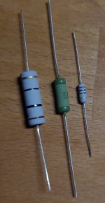
perhaps a 3 watt zobel resistor is big enough, dont know. I will try to measure the temperature. LJM uses 1 Watt on the original pcb, perhaps too small.
My 5 Watt, 3 Watt, LJM 1 Watt on the picture.
I have to look if i can take the Zobel and Coil near to the output. There is a little space near the backplate.
At first i have to measure the bias adjusting in the original L20SE to get a reference point. I assume about 40 mA, as i read in this thread.
The toshiba output transistors and the drivers are not very equal with their Hfe. I ordered original toshiba transistors at Mouser long time ago, but they have the same Hfe difference. Perhaps i can match with Vbe better...
Because of your advice i have made "Starpoint" pcb's. 😉
Greetings
Peter
Attachments
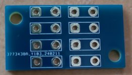
I'll also call this montage "Starpoint". 🙂Because of your advice i have made "Starpoint" pcb's. 😉
Hello,
I was not lazy. Mod pcb's and coils with their resistors are build in. Not much space for the big coils, but i think i have found a good solution. I took more time as i thought.
Before powering with the smps i will take a +-35 Volt testing supply. If i get no smoke i switch to the smps.🙂
Yesterday i tried to measure the bias adjust at my old L20SE pcb's. It was not possible. The bias wents up and down between 2mV and 4,9 mv. I tested for an hour. The reason may be the heatsinks. They didnt warm up, not a little bit. Dont know.
Good news..i had to drill nothing new. One transistor is a bit skew. I used the old Toshiba transistors fom the older original L20SE pcb. No chance to compensate something. The transistor connections were to short. Nothing to do with the function....
Testing will follow...
Regards
Peter
Attachments
![IMG_20240310_164442[1].jpg](/community/data/attachments/1192/1192209-2d22441b16245f28e765305415758771.jpg?hash=LSJEGxYkXy)
![IMG_20240310_164434[1].jpg](/community/data/attachments/1192/1192208-974d79f7a0ab085fca9aeb5a8ff5bd6d.jpg?hash=l01596CrCF)
Hi...
Today i wanted to test out the amp, one board first. I got some smoke from a 0,6 watt,100 ohm resistor, connected to transistor Q8, 2N5401 (was 2N5551 in).
I had to change Q8 and Q11. 2N5401 and 2N5551 were mistaken. There are wrong values on my pcb...i could find this mistake rather fast...
On the second try with changed transistors, no smoke appears and the bias setting was following the pot. But something is wrong.
I can't get the bias adjustment under 100 mV, end of pot. The 5 Watt zobel resistors is heating up and the drivers too. I testet only with the zobel network on the board.
I took out the 2Sd 669 out and test it, its ok...133 Hfe and Vbe 0,712 mV, equal to a newone. The pot is ok too i think. I can make a measurement.
I had a look to backside of the pcb and could not find a mistake in the connections or bad soldering. The resisistor values are right on their places.
Any idea what i can look for ?
Peter
Attachments

Of course i can change the 2 transistors on the second board before powering up, just to see if the problem is coming up on that board too.
Tomorrow perhaps, now is to late.
Tomorrow perhaps, now is to late.
Hi..
i know, but i cant believe that Hennady has designed an oscillating amp....
I wonder about the high bias. Do you see a connection between oscillating and high bias ?
Peter
i know, but i cant believe that Hennady has designed an oscillating amp....
I wonder about the high bias. Do you see a connection between oscillating and high bias ?
Peter
Cant you measure the output to understand if it's oscillating or if you simply cant bias it right?
Where is Hennady btw?
Where is Hennady btw?
Hi..
i own a oscilloskop..yeah...but i cant use it in the moment, must learn to use it. The second point...dont know if the L20SE is it worth to spend so much time.
I have made all mods in this thread now. The only problem, i got no 3,3 Ohm resistors. I put 2,2 and 1 ohm in series.
All outputtransistors got 3,3 Ohm resistors to their base.
I split off the inputground from the boardground/supplyground using an 10 ohm resistor. The feedback capacitors remains on supplyground.
Changed the 330 ohm resistor in the feedback to 680 ohm.
Put an 33p capacitor parallel on the 10K feedbackresistor
The 220µf caps got 100 nf capacitors, the 1000 µf feedbackcapacitor too.
For biasadjustment set a 1K pot in series with an 8,2K resistor.
Another Ground faston connector was soldered in.
I hope i have not forgotten something...
Greets
Peter
Attachments
![IMG_20240406_105453[1].jpg](/community/data/attachments/1203/1203368-1f037d4217930338299238b351f06d63.jpg?hash=HwN9QheTAz)
![IMG_20240406_105508[1].jpg](/community/data/attachments/1203/1203370-8061cd91e84b26eaece3d64d5b00db1e.jpg?hash=gGHNkehLJu)
![IMG_20240406_111528[1].jpg](/community/data/attachments/1203/1203375-f1bd8a490911b103994e79f9ed83cca1.jpg?hash=8b2KSQkRsQ)
Last edited:
You do not have an L20SE. Your product is very (and fatally ?) different from the L20SE.The second point...dont know if the L20SE is it worth to spend so much time. I have made all mods in this thread now.
It may not be exactly what you were looking for and, yes, it may not be worth investing a lot of time in.
No Sir...on the last pictures you can see the original L20SE. I have modded it as wrote down in this threads, the original board now. I will test it out.
See the original L20SE specifications, electrical diagram and board layout at the LJM L20SE Design Notes post.No Sir...on the last pictures you can see the original L20SE. I have modded it as wrote down in this threads, the original board now. I will test it out.
As you can see from that thread, there were already some forum members ready to criticise LJM and suggest circuit changes that sent more than a few amplifiers into oscillating & magical smoke territory.
Just by following the original design, I have never had an oscillation problem in all these years, let alone a magic smoke event. Just be careful never to test the amp without a proper load (loudspeaker or dummy) connected.
If I had to criticise anything about the original design, it would be the higher than necessary gain. Any cheap but well-designed DAC will output 2V these days, and this amp will easily overdrive with a 1.4V signal.
The amp with the original design was working, of course. But the sound was a bit loveless...
If i make a shootout with other amps of mine, the L20SE would loose. I am hoping the modding make something better to hear the L20SE with more joy.
Now i have build in the two boards in the old housing and test it first with +-35 Volt. If i get no smoke i will switch to the +-45 volt SMPS. I will try to lower the voltage to about 42 volt per rail.... the Connex SMPS allows +-3%.
I will test with shorted input and without any load on the output.
I will hear..or not...
If the amp dos not satisfy me....i through it away. Thats life and my own fault to buy an LJM L20SE Amp.
Peter
If the amp dos not satisfy me....i through it away. Thats life and my own fault to buy an LJM L20SE Amp.
Rest assured that this amplifier will serve you well.
However, even with the original Toshibas (TTA1943-PNP and TTC5200-NPN), the SINAD will never be better than 80 dB.
As for tweaks:
- Changing the R15 from 330R to 470R will reduce the gain a little and improve the SINAD.
- If you want to parallel the 220 µF caps to improve transients and speed, the 100 nF ceramic capacitors you're using won't help. You need good quality German polypropylene capacitors, such as Wima MKP 10.
- The C3 1000 µF does not need and should not be paralleled with other capacitors.
- If you really need to reduce heat, you can change the bias by replacing the R17 9K1 with an 8K5 or 8K2.
Last edited:
the Connex SMPS allows +-3%.
Connex make very good SMPS power supplies.
WARNING: The SPMS input ground should ALWAYS be connected to your mains earth lead at a point in the metal box of the amplifier near the IEC input socket. When an SPMS fails, mains voltage can flow into the amplifier chassis and through the signal connection cables (RCA, XLR, etc.) to any equipment connected to your amplifier, causing an electric shock which could be fatal to you or your loved ones.
The amplifier ground connections should be made to a single point on the SPMS output ground.
The RCA input ground should be connected with a very short wire to a point in the metal box of the amplifier near the RCA input socket.
If you want to know more about grounding, there is a very good paper on grounding audio equipment, written by a knowledgeable and innovative audio designer (of Hypex and Purifi amplifiers): "The G Word, or How to Get Your Audio off the Ground", by Bruno Putzeys
Hi..
no polypropylene capacitors in my stock in the moment. I have to order...
Don't be afraid. I know about electricity very well....not so much about electronic...
PE is always on the housing and on the primary and secondary side of the SMPS. Connex SMPS has a connection for the PE on the primary side.
In Post 345 you can see my starground..the second picture
Thanks for your advices...
Peter
Last edited:
Dear all,
After several years without visiting dyaudio.com, I was very happy to see how much you have done to improve the L20SE project. Congratulations!
@Hennady Kovalsky
@Kleinhorn
@XPZMIePKdFlkA
@A 8
After several years without visiting dyaudio.com, I was very happy to see how much you have done to improve the L20SE project. Congratulations!
@Hennady Kovalsky
@Kleinhorn
@XPZMIePKdFlkA
@A 8
There are two problems with this amplifier:
1. Noise riding on top of signal (see my post >>HERE<<)
2. Nonexistent bias
As a consequence this amplifier sounds dull.
The both problems have been addressed here but solutions are burried in a large number of posts. Problem 1. is due to too high gain, low bias causes crossover artefacts.
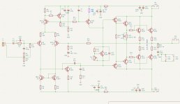
All you have to do is shown on the image below:
1. Replace 330R with 470R to increase feedback (and reduce gain)
2. Replace the 4K7 resistor with 5K potentiometer and adjust its resistance so that voltage between the output and emitter of any output transistor meassures 9-12 mV.
After the above simple changes, noise and crossover artefacts will wanish.

1. Noise riding on top of signal (see my post >>HERE<<)
2. Nonexistent bias
As a consequence this amplifier sounds dull.
The both problems have been addressed here but solutions are burried in a large number of posts. Problem 1. is due to too high gain, low bias causes crossover artefacts.
All you have to do is shown on the image below:
1. Replace 330R with 470R to increase feedback (and reduce gain)
2. Replace the 4K7 resistor with 5K potentiometer and adjust its resistance so that voltage between the output and emitter of any output transistor meassures 9-12 mV.
After the above simple changes, noise and crossover artefacts will wanish.
- Home
- Amplifiers
- Solid State
- Power Amplifier LJM L20SE