
In the same sense that a manufacturer's published specifications for a given transistor are of "academic interest only", because there will be (many) samples of those manufactured transistors that will not have "identical characteristics" to the manufacturer's published specifications...So the table is of academic interest only....
In the case of the capacitor table above, I am assuming that you are able to distinguish a tantalum from a ceramic or an electrolytic. Are you?
If so, what is this "identical characteristic" that allows you to distinguish them? Color, size, shape? Are you sure that you can claim, for example, that every tantalum capacitor will have that same color, size, shape, etc.? Same for all the others..
How is your "this table is too general" argument relevant to improving our DIY activities? Have you researched the subject and come up with a better, more objective and pragmatic table? Can you point us to the published paper or book?
Last edited:
Most of the "I think", "my feeling is", or "my experience is" come from people who are simply unable to point us to practical, objective, and verifiable published (or otherwise) work.
You are writing nonsense, think carefully if your patients demand that you or another doctor confirm your his diagnosis with publications on the Internet.Most of the "I think", "my feeling is", or "my experience is" come from people who are simply unable to point us to practical, objective, and verifiable published (or otherwise) work.
This is complete idiocy.
Last edited:
You are writing nonsense, think carefully if your patients demand that you or another doctor confirm their diagnosis with publications on the Internet.
Your statement, again, and like @batteryman's post, is a syllogistic fallacy construction. Let me rephrase:
"What patients demand, and indeed are entitled to, is that my diagnostic hypothesis be based on sound, published, and verifiable scientific work."
There is nothing wrong with a patient searching the Internet (unfortunately, most of the time it is limited to Dr. Google), because if the diagnosis is based on solid knowledge, the patient will eventually find arguments that support it.
I know that (Electronics) Engineering Is Not Science, but it is still grounded in practical, objective, and verifiable published work.
Asserting oneself through impolite and confrontational behavior does not strengthen a weak argument."This is complete idiocy."
While on the subject of electrolytic capacitors, I would like to draw your attention to a recent article: "Selecting Electrolytic Capacitors for Lowest Distortion, by Douglas Self", published in Audioxpress (to find the article, search for 'Editor's Desk' in that page).
Last edited:
DS writes - "THD was measured at full boost and 10 Vrms out, just short of clipping, and with C2 as a 22/63V part there was. 0.0008% at 20Hz; without the capacitor you get 0.0006% With a 22/35V part you find a rather less appealing 0.0023%."While on the subject of electrolytic capacitors, I would like to draw your attention to a recent article: "Selecting Electrolytic Capacitors for Lowest Distortion, by Douglas Self", published in Audioxpress. (To find the article, search for 'Editor's Desk' in that page).
His conclusions correspond absolutely exactly to the results of my university work 10 years ago on the selection of electrolytic capacitors. Moreover, I also had mathematical calculations with differentials using a specific example.
So, what is next? What do I need to prove on the forum to a "radioamateur doctor" on the forum with the nickname "abrakedavra"?
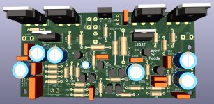
My pcb's had arrived. But i had to register that some coponents need more space, to near to others, the final pcb was not the final. 😕
I had to made three changes.
For testing i could use the pcb, but thats not my claim. I have done the necessary changes in Kicad and new gerber files are uploaded...
Good news..the holes on the pcb for the transistors and screwholes are similar to the original pcb.
Especially the 0,22 ohm resistors need more space to the other components. I have made a own version in the foodprint editor and tested the necessary space.
For other projects i will save such a footprint in the libary, because the change only is not shown right in the 3d view.
I guess it takes a little bit more time to build the mod...
Peter
Attachments
Hello Peter!Peter
Please post a diagram with the values that will be on the new board with the tweak. So that I can check the modes in more detail and, if necessary, adjust the compensation and general settlement.
During this weekend I made 2 tweaks with progressive compensation and was able to test their sound.
Since the amplifier circuit topology is almost the same as yours, I think you can spend less time on setup. And be satisfied with the comfortable sound.
P.S. If you have questions about the features of progressive compensation circuits, in order to understand their effect, ask.
Hello Hennady,
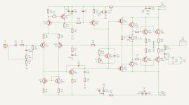
what do you mean with a diagram with the values ? I hope you want to get the schematic ?
In appending to the schematic my new pcb.
You know i have not much ideas of electronic, but you can try to explain the progressive compensation you made. If i take google to search for "progressive compensation in an amp" only rubbish is the result...
Greetings
Peter
Attachments

Yes. that's right.Hello Hennady,
what do you mean with a diagram with the values ? I hope you want to get the schematic ?
In appending to the schematic my new pcb.
Thank you.
Progressive compensation is the process of changing the frequency characteristics of a signal in the range from 1 kHz to the unity gain frequency using links of zero (R) and first order (RC) circuits.but you can try to explain the progressive compensation you made.
application options
1st compensation in the local feedback circuit
2nd compensation outside the feedback loop
3rd combined option (outside the loop and in the local feedback loop)
* according to the 1st option, everything is clear - this is Miller’s common compensation.
The main application is operational amplifiers, because such compensation is stable at any gain from 1 or more.
* according to the 2nd it is applied for a certain gain, because Ku is included in the calculation of the parameters of the RCRC circuit.
An amplifier is an amplifier to amplify sound, therefore, unlike operational amplifiers, audio power amplifiers have a completely fixed gain
The calculation is based on the "state variable method" for calculating filters. The state variable method is based on the orderly composition and solution of a system of first-order differential equations that are resolved with respect to derivatives.
Most common in audio the second option for progressive compensation is "Loudness" compensation in the audio frequency band;
in our case, the amplifier compensation frequency configured an average of 700 kHz.
The filter of acoustic systems is also calculated using the method of variable states.
the implementation of the 2nd option was first seen in the scheme of ours with you fellow countryman Michael Wiederhold in 1977, and began to be seen more often in schemes after 1998...
* 3rd. A combined compensation option is used in the case when, when controlling a push-pull output stage, its input resistance at high frequencies becomes either equal to or less than the load resistor of RC-shunt - at the input of the power output stage.
I see the implementation of the 3rd option in Cordell’s some diagrams
Hello Hennady,
i think i could follow..not in detail, but i can understand that is negativ in an amp with a static input gain and I know a little about loudness with fixed filters.
The third case i dont understand yet. No idea how i could work "its input resistance at high frequencies becomes either equal to or less than the load resistor of RC-shunt"
But i trust in you. It seems you have a big knowhow in designing an amp or making a mod to an other amp.
Thank you very much
Peter
This can be seen in the open-loop frequency response if, with increasing high frequency, the gain changes sign from decreasing to increasing, this is a complex variable. and this means that one of the amplification stages (usually the first) amplifies a wider frequency band than the next one, if the resulting high-Q peak in the frequency response cannot be corrected by increasing the gain of the first stage or reducing the gain of the second stage, then it is necessary to add compensation in the negative circuit feedback, and this is not from the output point of the amplifier, but this is either a high-impedance point - the point of operation of the voltage amplifier at the output stage, operating in class A, or for example, the first stage of the Lokanti output stage follower.The third case i dont understand yet. No idea how i could work "its input resistance at high frequencies becomes either equal to or less than the load resistor of RC-shunt"
Of all the options for compensation solutions, only single-pole correction using zero or 1st order circuits ensured ideal sound reproduction on any music.But i trust in you. It seems you have a big knowhow in designing an amp or making a mod to an other amp.
The most important condition is that this amplifier compensation pole does not fall within the range of maximum human hearing sensitivity - this is 300Hz-3kHz.
Those. so that the pole is will by:
* in the frequency range 120 - 300Hz for the first compensation option (I also do not recommend below 120Hz, because in acoustic systems the low-frequency speaker begins to work with the linear stroke of the diffuser, and it is very important for the quality of reproduction of low frequencies that the depth of negative feedback be linear )
*pole at compensation in the frequency range from 3 kHz and higher - for the second and third compensation options.
Last edited:
Good morning,
i can follow a liitle bit.
I only know about negativ feedback from the output to input, using a resistor or resistor with capacitor. One stage only.
The second think i know is to watch out that the negativ feedback is not driftting to a positive feedback by phaseshifting.
If its possible to get more dynamic in the feedback, i can imagine that is a other, better way.
Don't know how it can work with more compensationpoints, not in the moment.
Greets
Peter
Hello Henneday,
found your thread https://www.diyaudio.com/community/...ifier-with-symmetrical-topology.409356/page-2
Now i can see something clearer.
found your thread https://www.diyaudio.com/community/...ifier-with-symmetrical-topology.409356/page-2
Now i can see something clearer.
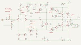
Hello PeterHello Henneday,
look at the attachment.
* denominations that should be replaced are red highlighted
*additional - must be added сapacitor "Сextra" parallel to R1
- gain resistor R12 reduced before 510 Ohm
- Capacitor C5 should be increased in value before 330uF min, this will reduce 5,7,9 harmonics in the distortion spectrum.
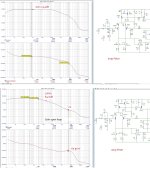
The gain pole turned out to be at 1.8 kHz, but if you look at the linearity of the open loop gain in the range of 300 Hz - 3 kHz, it is +/- 3 dB. that's not bad either.
Attachments
Last edited:
- Home
- Amplifiers
- Solid State
- Power Amplifier LJM L20SE