Hi A8,
perhaps you can take a look to the LJM L20.5. That amp is sounding very well. One thing, i have read,
Transistor T9 has to get 300 pf 500V ceramic instead of 100 pf (millercapacitor). https://tonbandforum.de/showthread.php?tid=26889
Sometimes the driver transistors have changed. The chinese people build in what they get.
https://www.diy-hifi-forum.eu/forum/showthread.php?20484-Vorstellung-LJM-L20-5-Amp. The user Saarmichel has build the L20.5 in BTL.
Output stage of my L20.5 are the KEC Transistors. You can also choose 2SC5200/A1943 or similar...
https://www.diyaudio.com/community/...st-data-my-design.323965/page-11#post-7469238
A few years ago i could hear my L20.5 on Manger Speakers https://mangeraudio.com/de/systeme/produkt/p1-de
The L20.5 has driven this speakers easily. Not every amp can drive this speakers with clear and brialliance sound.
Peter
Last edited:

Hello Peter!perhaps you can take a look to the LJM L20.5. That amp is sounding very well. One thing, i have read,
Transistor T9 has to get 300 pf 500V ceramic instead of 100 pf (millercapacitor).
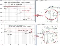
I hasten to warn you that increasing this capacitor from 100pF to 300pF reduces the gain of the input stage at a frequency of 20 kHz and therefore its linearity deteriorates by 6.4 dB, which is a lot. Because The input stage gain at frequency drops from +5.4dB at (100pF) to -1dB (300pF).
In this case, the pole is the frequency at which the output impedance of the amplifier begins to increase at 100pF = 740Hz, and at 300pF = 252Hz.
It is possible that an indirect improvement in sound occurs due to an increase in output impedance in the frequency range of 250-800 Hz, but one must understand that in this case the nonlinearity of the frequency response increases. The sound becomes specific.
Can it be improved with the L20.5 mod? yes, but not by increasing the miller capacitor from 100pF to 300pF.
Last edited:
There is another reason why the sound with a 300pF Miller capacitor is perceived better by ear - this is the limitation of the HF spectrum when controlling the Shiklai output stage, this almost always reduces distortion at HF, perhaps this is associated with an audible improvement in sound.
and from here comes the logic of the modification of this amplifier, adjust the amplifier so that, on the one hand, it does not reduce the linearity of the input stage, and on the other hand, limit the control spectrum of the Shiklai output stage.
and from here comes the logic of the modification of this amplifier, adjust the amplifier so that, on the one hand, it does not reduce the linearity of the input stage, and on the other hand, limit the control spectrum of the Shiklai output stage.
Hello Hennady,
thanks for your warning. It seems to be not a good idea to change the miller cap. No fear, i havent changed anything. I am satisfied with my L20.5.
"Never change a running sytem" in some case true...
You see..i have to learn a lot...
I will write your statement to one else, because he decide to do..
Peter
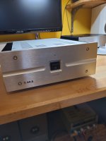
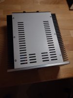
Pictures of my L20.5...
Top aluminium plate was laser cut, very interesting..time 30sec...i could see a video...
The case bought on Ali Express i found never again. The shop was banned, the reason i dont know.
No more pictures of other amps in this thread now...
I am waiting for the delivery of the L20SE kits, measure and send the zip files to jlcpcb...exiting...
Attachments

Ok, and I too think it should be good for the surrounds if I could get rid of what I assume is power-supply harmonics. The odd thing with it is that it seems to be more harmonics over 500hz at the output compared to what's on the rails.I'll have to disappoint you, mods will bring the circuitry to life in terms of load characteristics, but for high sound quality I think this solution will not be enough.
But Surround Sound Stage will work better with these mods.
Any idea if this would be cleaned up with the mods you suggested?
No Signal FFT speaker output:
This is the supply voltage FFT taken directly on the rail+- 40 volts and yes I have them filtered so its pretty good. 0dBFS is around 3 volts RMS on the "no signal FFT" and around 10 volts relative to 80 volts DC across both rails on the below FFT:
Attachments
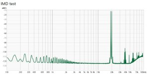
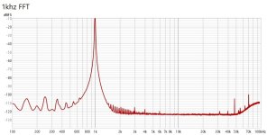
I think so, in the second picture you can see the power harmonic at 100 Hz, this is what comes from the amplifier’s power supply, so you need to check the zero voltage at the amplifier output, the initial current of the output power transistors, as well as the grounding wiring in the case.Any idea if this would be cleaned up with the mods you suggested?
I have been thinking it was a ground problem for a long time and have made changes over the last few months to see if it makes a difference but it does not matter what "sane" changes I did, it stays pretty much exactly the same. Cant be heard though, even close to the speaker its silent.
Anyways, I have 8 unpopulated pcb's on order now so will try out the mods and see what it does to the measurements and sonics.
Thx.
Anyways, I have 8 unpopulated pcb's on order now so will try out the mods and see what it does to the measurements and sonics.
Thx.
Here is an example of modding the MX50SE using progressive correction, see attachment. This is the effect of correction on the linearity of the input stage. Therefore, when I did this, everything sounds very clean and beautiful...)))You see..i have to learn a lot...
I will write your statement to one else, because he decide to do..
Peter
HenK
Attachments

At the first look, simple.. but not for me 😕
I have to learn a lot. If my last projects done, i first will take my new scope, remaining here over one year unused, learn to use it. I have done never before, not necessary in my life until now, but heard from it...😀
I have to read a lot, get my first book about circuit technology.
And so on...
Best regards
Peter
I also strongly recommend reconsidering the design preferences when laying out the grounding wires of the GND, because linear and broadband amplification will require minimizing power supply and grounding wire loops.At the first look, simple.. but not for me 😕
I have to learn a lot.
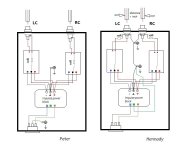
The methodology that you use is relevant for monoblocks, when each channel has a separate power supply. This book was written when large tube amplifiers were being manufactured as monoblocks, but in an integrated design, when there is 1 block power supply for 2 channels,the absence of an additional ground loop between the channels is of great importance; in this case there will be no desire to “listen to the wires” and their effect on the sound.
Unfortunately, your design has a lot of unnecessary ground loops.
HenK
Hi Hennady,
i try to make some things better and read articles "to provide groundloops on pcb layouts". I have make changes yet, dont know better in the moment.
Peter
i try to make some things better and read articles "to provide groundloops on pcb layouts". I have make changes yet, dont know better in the moment.
Peter
We are not talking about printed circuit boards, but about connections inside the amplifier housing.i try to make some things better and read articles "to provide groundloops on pcb layouts".
Okay, you can only learn everything from your own experience.
Henk.
If my L20.5 is powerd i cant hear no hum or withe noise at all in my speakers. There is dead silence.
You think that there are groundloops because i have only one smps for powering the boards ? I can build a "starground" with one pcb in front of the smps.
That is a possibilty to cut the second connection to the output. The protection board only need one ground connection to measure.
Peter
You think that there are groundloops because i have only one smps for powering the boards ? I can build a "starground" with one pcb in front of the smps.
That is a possibilty to cut the second connection to the output. The protection board only need one ground connection to measure.
Peter
Hello Peter!
Attached are design options
maybe it seemed to me - on the left is your option
On the right is my version of the design - this version is currently working for me at home.
Can you comment? Maybe I’m still wrong and yours is not turned on correctly and I’m also not designing the wiring of the grounding wires correctly.
Attachments
this is how it should be, but the problem is the increase in the capacity of the interconnection, this is not hum or noise, it is HF interference from the interconnect wire to the input of the amplifier.If my L20.5 is powerd i cant hear no hum or withe noise at all in my speakers. There is dead silence.

- Home
- Amplifiers
- Solid State
- Power Amplifier LJM L20SE