their use depends on the routing of ground wires inside the amplifier. If the input grounding wires are connected at the housing, then they must be used to break the circuit; if there is no grounding connection at the amplifier input, then through these resistors I ground the wires at the input terminals to one point.The resistor 10 ohm splits the powerground to an A ground. Dont know if nessary.

Hi,
thank you very much. I will make the changes with the resistors to base and put a 220nf in. If the A Ground resistor is not necessary, i can shorten it. I want to use an +- 45 volt 500 watt Connex smps, witch ist built in already. There is no ground contacting to the housing. Always i use a protecting earth connection to a metal housing, no connection to smps ground or rca ground.
If the inductor and the two resistors are not necessary, only the zobel remains on the pcb. More space...
Thank you, very kind you took a look. If the changes are made i attach new files...may be it will take a few days...
Greets
Peter
Everything is fine, please make a grounding connector for output to the speaker system from the board, so there will be less distortion.Always i use a protecting earth connection to a metal housing, no connection to smps ground or rca ground.
The main goal of minimal distortion is greater design versatility, in which the growth of distortion in case of unsuccessful installation can increase at least 10 times. Because it will not change the quality of the perceived sound.
There are a few things I would add to your PCB:
heatsinks on the 2SC5171 / 2SA1930. If you plan on running them at ±45V, idle dissipation can get relevant (0.8-1W). At the usual 62.5C/w in air for to220 we're getting significant temperatures. Better to keep them cool and limit thermal effects.
5W output resistors, depending on what you can get for your project or if you're using the default ones. You might not get enough space if you're using the ceramic "blocky" ones
Possibly some rail decoupling locally. Nothing massive, just 100 or 220µF on each rail, with good and short (low inductance) traces to the power transistors.
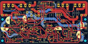
Rotate C5 180 degrees to shorten the length of traces. Make the GND output terminals next to each other , and place the terminal for the output to the OUT speaker system where the GND terminal is located.because i know i can not sleep without making the corrections ...
Its your mod Hennaday. I put your name on the board ?
A good point is that, if there is 1 watt of heat dissipation, then a large radiator area is needed, more than a compact arrangement of small radiators. Therefore, it would be better to increase the depth of the boards so that there is more space for these transistors to dissipate heat.heatsinks on the 2SC5171 / 2SA1930. If you plan on running them at ±45V, idle dissipation can get relevant (0.8-1W).
Also, it is better to set a load resistor of 100 for this pair of transistors to 5 watts, it is the main one for high-quality operation of the output stage.
Last edited:
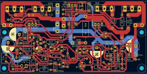
The feedback is taken from the wrong point - it should be from the output connector, otherwise non-linear currents will combine with trace resistance to give error voltages seen by the feedback pick-up point. Even those thick traces have a lot of resistance (compared to an 8ohm load), perhaps 0.01ohms, which is only 58dB difference (52dB for a 4 ohm load). This will limit the distortion values under load to that sort of order. -60dB distortion is 0.1%
Thinking more about the layout - use some back-side traces to prevent contorted front-side traces, and the rest of the back side can be ground plane, making ground much more well defined.
Thinking more about the layout - use some back-side traces to prevent contorted front-side traces, and the rest of the back side can be ground plane, making ground much more well defined.
Last edited:
Hi Andrea,
i know aubout the heatsinks for the drivers. Kicad doesnt have the right ones. There is enough space for some heatsinks. Perhaps i choose a hole to fasten.
Adding capacitors 220 µf is done...grounding connection to output..done
Its late now...more changes i can make in the next days. One driver has got more space for an heatsink. On the left side.
One question you have not answered yet...Groundplane or not ?
God night and thank you very much...
Peter
Attachments
Also, it is better to set a load resistor of 100 for this pair of transistors to 5 watts, it is the main one for high-quality operation of the output stage.
Sorry my english is not so good. What do you mean ? Two 5 W resistors more to the drivers ?
Attachments

like this, see attachmentOr put it in the rail voltages to the drivers ?
I'm only talking about the power of R23
Attachments

Hallo, Peter!Hennady, thanks a lot, very kind...
I hope its the last change to do 😉
Yes, I think the board is now ready for a trial run of the project.
P.S. need to select radiators for the driver stage
HenK.
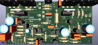
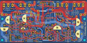
Peter, Could you show a pic of the board in # 232 but with Silkscreen selected so it will show the components clearer. That would be helpful.Sooo...last changes for today...
Feedback resistor to output and groundplane...
God night every helping member..great...
Peter
Scott
Attachments

Hi Scott,
last changes today...i made a screenshot with silkscreen view.
Hi Hennady,
i will think about the driver heatsinks of course. I ordered two more kits on Ali Express, heatsinks included, i hope. Toshiba transistors i have ordered at mouser and in germany at reichelt company. I hope i can match the Toshiba transistors to get pairs.
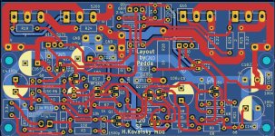
I put a bigger resistor in for R23, 3 or 5 watt. R22 had to grow too on the pcb. Some lines i made shorter. I hope thats it....
Greetings from Germany
Peter
last changes today...i made a screenshot with silkscreen view.
Hi Hennady,
i will think about the driver heatsinks of course. I ordered two more kits on Ali Express, heatsinks included, i hope. Toshiba transistors i have ordered at mouser and in germany at reichelt company. I hope i can match the Toshiba transistors to get pairs.
I put a bigger resistor in for R23, 3 or 5 watt. R22 had to grow too on the pcb. Some lines i made shorter. I hope thats it....
Greetings from Germany
Peter
Attachments
Is this gonna be a kit? Or sell boards for the forum? We need to get it tested out! Looking forward to some fun! Thanks for your time and effort....
- Home
- Amplifiers
- Solid State
- Power Amplifier LJM L20SE