First time valve amp
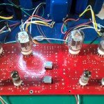
Finally got round to finishing the PCB build on this and powered it up. Luckily had no problems. Valves balanced all OK and when playing through some old Kenwood speakers the sound quality was excellent. Still building the box as you can see in the picture. I hope to have this finished soon. Thanks Pete for a great design and very easy to follow for a newbie
i need to get some good speakers for this amp. What are others using. I want book shelf speakers and was thinking about the KEF Q300 which have 87db sensitivity. Anyone recommend these or do I need to go higher on the sensitivity.
Attachments
Just finished putting my amp together into the box. Powered it up and all looked good. Tubes glowing away but no sound, then the magic smoke started coming out of the PCB. Would be a good effect but no its the components doing it and this is not good.
So I am a little sad today as the amp is now out of action. It was working all ok until I installed it into the case. After some testing I have found Q1, D5, D6, D7, D8 all shorted out. R21 got real hot but seems to have recovered and is still showing 4.7K. I've ordered new parts and so this can all be repaired, but the worry is why they shorted in the first place.
Changes I made from when it was working to the dreaded smoke affect. I had to reconnect the transformer wires through the holes and the chasse earth. All valve plate wires where extended and the MOSFET's were extended and attached to the metal plate.
All wiring looks ok so I can't see that being a problem. One of the MOSFET's got a little too hot when extending the wires so this could be the problem. Also I need to know if the MOSFETs need to be insulated when attached to the metal plate. I know some MOSFETS have the source to the backs. If so then this would explain the short circuit.
I am also not sure why all the zenor diodes shorted out. If the MOSFET had a short from drain to source then why would the zenors short need to look up the voltage rating of these. Finaly would the valve screens have been damaged. I don't know how to test these.
With all the failed components removed I have powered up again and the B+ circuit is working all ok. Just need to wait now for the replacement components and start again.
Any help advice on why this went wrong and what I need to check including the valve screen would be much appreciated.😕
If the mosfets you used in your build have any exposed metal on the cases, they must be insulated from the chassis. As you guessed connecting them to the chassis shorts out the B+ supply.
There are mosfets that are completely enclosed in plastic. These don't require insulation.
There are insulation materials specifically made for TO-220 mosfets as well. You need to use one of these method to avoid future smoke.
There are mosfets that are completely enclosed in plastic. These don't require insulation.
There are insulation materials specifically made for TO-220 mosfets as well. You need to use one of these method to avoid future smoke.
Steve8428, I had the same issue. Even though I have the plastic encased mosfets, I had not secured them to the chassis in anyway. So R21 got very hot and smoked on me. An email to Pete Millett and this newbie learned I need to have the mosfets making physical contact with the chassis plate and ensure the mosfets also have thermal compound between them and the plate. So I probably fried the mosfets. I have not yet begun to troubleshoot as I am preparing to travel. But when I get back I will begin checking my board. I won't be surprised if I have same parts shorted out that you have.
Just removed my MOSFET and it is the plastic type. I did have it secured tight to the metal plate but looks like not much thermal past. I expect the damage was done when I soldered the extension legs to the MOSFET as it got very hot (soldering iron set to high). if this is the case then it's all an easy fix. My only worry is if the valves screens got damaged. Is there a way to test them.
Thanks tubelab for the advice I will look at getting the insulation material as a precaution. I am also away so won't be doing any repair for at least a week.
Thanks tubelab for the advice I will look at getting the insulation material as a precaution. I am also away so won't be doing any repair for at least a week.
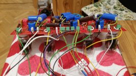
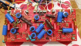
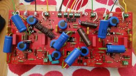
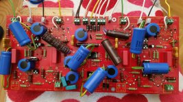
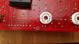
Hi all, so after some months have had time to complete the red board (photo1 and photo2).
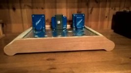
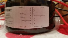
I’m doing the version using 6HJ5 and a slightly tougher power transf (photo3) [toroidal custom made]
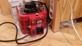
First powers up were made using a variac (photo4), when nothing exploded made the bias adjustment following Millett’s web
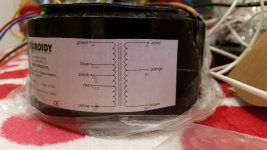
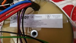
The output transformers are 3.3K custom made too (photo5)
Now, I have a big hum problem, something must be missing or incorrect.
With no input attached there is a faint hum through the speakers (4 ohm impedance).
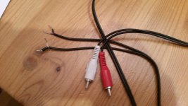
Simply putting an input cable (photo6) with no source attached make the hum grow considerably.
Trying to connect a preamp (an Aikido preamp) makes A LOT of hum.
Must have done something wrong or there’s something missing.
1) Someone had same problem? Any suggestions?
2) Output transformer : being a push-pull amp, am I correct using the A1,A2 (Anode, suppose) instead of UL1, UL2?
3) At the moment there is no chassis so no chassis ground : so where should I use the ground loop breaker suggested by Pete?
Thanks
I’m doing the version using 6HJ5 and a slightly tougher power transf (photo3) [toroidal custom made]
First powers up were made using a variac (photo4), when nothing exploded made the bias adjustment following Millett’s web
The output transformers are 3.3K custom made too (photo5)
Now, I have a big hum problem, something must be missing or incorrect.
With no input attached there is a faint hum through the speakers (4 ohm impedance).
Simply putting an input cable (photo6) with no source attached make the hum grow considerably.
Trying to connect a preamp (an Aikido preamp) makes A LOT of hum.
Must have done something wrong or there’s something missing.
1) Someone had same problem? Any suggestions?
2) Output transformer : being a push-pull amp, am I correct using the A1,A2 (Anode, suppose) instead of UL1, UL2?
3) At the moment there is no chassis so no chassis ground : so where should I use the ground loop breaker suggested by Pete?
Thanks
Attachments
....For some reason I have 24V AC on input, that's the cause of Hum.
Removing all tubes and output transf change nothing, still 24V AC on input.
Where does it come from and how debug it????
Removing all tubes and output transf change nothing, still 24V AC on input.
Where does it come from and how debug it????
24 vac ? did you connected the feedback loop, maybe it is reversed polarity, don't worry it happens to the very best of us.
check the input tube grid V to cathode. and how much current it is pulling, check B+ and anode resistor integrity.
check the input tube grid V to cathode. and how much current it is pulling, check B+ and anode resistor integrity.
Last edited:
Hello All. I need some help with the +150 Screen regulator. It was working ok till i connected it all to the chassis and some how blew up Q1 D6, D5,D7, D8. i have since replaced all components. Now when powering up with out the tubes connected the screen voltage is reading the same as the supply voltage. So its not regulating the voltage. All zenors are connected the wright way round and no shorts. the voltage on the Zenors D5 to ground is over 150V. Any ideas what went wrong.
found the problem. i had a dry joint between D7 and D5 so no regulation. resoldered and now amp working again.😀
Still Hum from red board
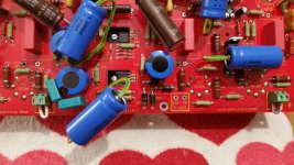
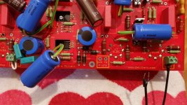
Here.....still with the big HUM on the red board (photo1 and photo2).
I’m doing the version using 6HJ5 using custom EDCOR power transformer.
Output transformers are 3.3K custom made.
There is a big hum problem, something must be missing or incorrect :
Touching left or right input with a metal make the hum grow considerably.
Trying to connect a preamp makes A LOT of hum.
Measuring AC between AC GND and IN (right or left) get around 30V AC
Disconnecting AC GND cable, the hum is still there.
Made a couple of videos, here :
https://youtu.be/T3pmwwjFoOE
https://youtu.be/FTGDwC7-n5Y
Thinking that Q1 or Q2 may be wrong, how to check?
Any other idea?
Thanks
Attachments
Yesterday double checked diode orientation
Checked capacitors orientation
Changed Q1 with a new one
Changed input tubes (6CB6) on one channel
NO change in hum
Checked capacitors orientation
Changed Q1 with a new one
Changed input tubes (6CB6) on one channel
NO change in hum
Place a small wire in the input block to connect the two terminals (Gnd and IN). This will short the input to ground, is there still noise?

Correct. Let's try only one channel at a time.
So, just tried right channel, (photo and video_1) there's same hum.
Video right ch : https://youtu.be/GPc9Te02h6M
Tried left channel (video_2), unlikely same result.
Video left ch : https://youtu.be/XDCX3hDdKk0
It seems that hum is present independently on both channels.
Just to be sure : I'm using toroidal P-P output transformers, I understand I should use the A1 and A2 wires + black for B+ (photo attached)
Attachments
Last edited:
- Home
- Amplifiers
- Tubes / Valves
- Posted new P-P power amp design