I have been neglecting this project for some time as I had been trying to determine how to assemble the chassis but have decided forget about that and just get it working and then focus on the aesthetics.
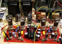
I came to the same conclusion, so I have just screwed everything to a piece of plywood.
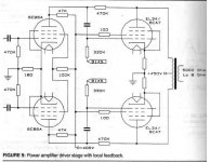
- Change 220k ohm schade feedback resistors(R29, 30, 31, 47) to 2-3 two watt resistors in series to handle the voltage spikes
!!!!!!!THIS ONE IS IMPORTANT!!!!!!!
These resistors are going to see peak AC voltages approaching twice the B+ voltage. Even if you built your board to Petes original specs that could be 650 volts or more if you hit hard clipping. Petes BOM states 1/2 watt minimum but calls for a 2 watt resisitor. The Mouser part number called out is rated for 500 volts "absolute maximum working voltage" and 1000 volts "absolute maximum overload voltage". Those of us that tend to crank the board up a bit can see 1200 to 1400 volts across these resistors. I used some old 3 watt BC Components that I had leftover from building some Tubelab SE's. There has never been any indication of distress on these parts but NONE OF THEM measure 220K anymore. The best one is 240K and one is 300K. Maybe this is why I had to keep readjusting things to lower the distortion.
-Change R48, 49 to 10k 3watt
Don't do that. Yes I increased this resistor several times after exploding one cap, and frying another, but that was when I was feeding 500 to 650 volts into the entire board. The new plan calls for running the board on 300 volts, which is lower than Petes original design. I have put a 1K back in my board. It WAS working fine.
-I had purchased a few of these mosfets a while back with the idea they would work with the red board.
I got some of the big Fuji FETs too. The leads are too fat to fit through the holes in the board, so I used two all plastic Toshiba fets. Al ill fated attempt to measure something on a live board cause one of them to release its smoke and some of its silicon so the board is now dead. Digging for a suitable replacement now, maybe I'll just stick in the Fuji's aince I know where they are.
-create FWB for bias supply utilizing 44v secondary off of transformer
You need a FWB for the bias winding and one for the main B+. I used the diodes on the PC board for half of each bridge, and soldered two additional diodes on the opposite side of the PC board for the other half of the bridge. This way the entire main power supply is resident on the PC board. I am currently using just the blue wires for the bias supply and I get -55 volts. THis works fine for the E130L's that are in the amp now, but I think adding one or two of the extra filament wires in series for a little extra might be needed for the big sweep tubes.
-Omit the 820pf capacitors C7, 9, 10, 15
There is another thread here about a compactron amp. The builder had one of these caps fry and it was rated for 500 volts. The same comment applies here as the feedback resistors. They will see BIG VOLTAGE. It is best to leave them out.
Now for the power supply I have yet again drawn up another amateur attempt.
That is exactly how my board is wired today. I have not installed the BFC's yet, I am using the caps on the PC board. In fact the entire bottom half of the power supply is entirely contained on the PC board. The CL90 is going to be needed....if it doesn't blow up trying to cope with the charging current of the BFC. There is already one on the board for the lower supply. I would use something larger than a UF4003. The UF4003 is only good for 200 volts. I used UF5408's bcause I had them (their leads are too fat for the board) but UF4007's are OK.
The top half of my supply is just 4 diodes and two caps on a piece of perf board. I should add the CL90.
I might get this thing fired up this weekend.
For some reason I had the UF4003s in mind and it could have been from the BOM but I meant to put the MUR1100 parts into my diagram. My intentions are to have on the lower chassis the first half of the power supply and connecting to the pad of c6 on the board leading to the ripple filter. I am still debating using those large caps, they do take up a lot of space.
I am going to run out to home depot hopefully tonight to pick up some standoffs for the board so I can screw everything down but have it some what accessible.
I am going to run out to home depot hopefully tonight to pick up some standoffs for the board so I can screw everything down but have it some what accessible.
Last edited:
I am still debating using those large caps,
I will try them after everything else is working.
I found the BFF's (Big Fuji Fets) but I can't find the insulators...So I am installing a new set of Toshibas. It's the lazy way.
OK, As of 10:30PM both power supplies are working, but not connected together yet. I now know that I wasn't thinking too well when I threw the fets on a heat sink and stuck them in the PC board since the heat sink covers up some parts. Of course I took it all apart, replaced the blown fet, and put it all back together. It still didn't work. I started with zero volts of B+ and wound up with 28 volts. C30 was in backwards. Of course it was under the heat sink. One more time.
I now have 285 volts of B+, 155 volts on the screens, and -55 volts of bias. This is with driver tubes but no output tubes. I spent about an hour trying to figure out why I only had 55 volts on the plates of the drivers where 150 volts used to be. DOH, no OPT's. The drivers get most of their voltage through the Schade resistors, which are supplied through the OPT's. I wired up some OPT's and connected their red leads to a power supply set on 550 V and all was normal. Voltages were all good, but no output tubes are installed yet.
I have a self imposed 10PM cutoff time for playing with electricity when no one else is home, so it's on hold for now. Tomorrows plans depend on the weather. If it's nice outside, I have some horn speakers almost finished. I need 6 hours or so to complete them.
Sounds like my self imposed "cellphone must be out of pocket but within reach of both arms" when working under cars or with the table saw.
I have my son populating tagboards now for his P2P version with 6HJ5 (B+ 400 volt). For the bias supply and the screen supply we chose for one diode bridge each. After that we make separate supplies for each channel (so 2 screensupplies and 2 biassupplies).
I wonder if I need heatsinks for the mosfets (IRF820) in the screensupplies because each one supplies just one channel. I use a 200 volt winding on the powertransformer and change the zeners for two 0A2's.
I suppose there is a formula for everything but I do not know them 🙂
I wonder if I need heatsinks for the mosfets (IRF820) in the screensupplies because each one supplies just one channel. I use a 200 volt winding on the powertransformer and change the zeners for two 0A2's.
I suppose there is a formula for everything but I do not know them 🙂
Sounds like my self imposed "cellphone must be out of pocket but within reach of both arms" when working under cars or with the table saw.
I don't know, my cell phone is usually in my pocket when using the saw, and well out of the way while under the car (I'll break it).
Some things you learn by experience like keep your long hair away from the fan belt of a running engine! Some things like 650 volt 1.7 amp power supplies are best not experienced! My wife and I have noticed an obvious drop in my attention span, vision and motor skills after about 10 PM. Seems to be getting worse as I get older.
I wonder if I need heatsinks for the mosfets (IRF820) in the screensupplies because each one supplies just one channel. I use a 200 volt winding on the powertransformer and change the zeners for two 0A2's.
A 200 volt transformer winding should result in about 275 volts of DC. You want the screen supply at 150 volts. That means the mosfet needs to drop about 125 volts. At about 50 mA the mosfet will dissipate about 6 watts. The current and heat will be less at idle. I would say that a small heat sink or mounting to the metal chassis should be OK.
.
1- Change 220k ohm schade feedback resistors(R29, 30, 31, 47) to 2-3 two watt resistors in series to handle the voltage spikes
2-Change R48, 49 to 10k 3watt
ad 1: That is why I am a P2P believer, I can change 1 x 220K into 2 resistors 😀
ad 2: What do the experts think of giving the 6CB6 a bigger Plate resistor, as in this Schade design that has B+ of 450 volt. I realize that there is a connection with the feedbackresistor, I will see what happens.
Attachments
My wife and I have noticed an obvious drop in my attention span, vision and motor skills after about 10 PM. Seems to be getting worse as I get older.
Well, you and your wife could do the more difficult things on a different time

By the way, thanks for your good tips

What do the experts think of giving the 6CB6 a bigger Plate resistor, as in this Schade design that has B+ of 450 volt. I realize that there is a connection with the feedbackresistor,
In a typical pentode amp increasing the plate load resistor within reason increases the gain. In this design there are 3 different forces at work here. Increasing the plate resistor increases the gain, but also increases the Schade feedback, and lowers the plate voltage. In my first version of this board the plate supply was 450 volts and I increased the plate resistor to 39K to get a bit more gain. The Schade resistors are still 220K but are partially fried. The 39K value was found by increasing the value until the distortion went up at full power. I was attempting to crank 250 WPC out of the board and was being limited by drive voltage.
I think that the plate resistor and the Schade resistors would need to be tweaked for each individual situation but the original values are a good place to start.
I now have the board running with 280 volts of B+ and 550 volts on the output tubes. It still seems to work quite well with all of the old resistor values but I am running very sensitive output tubes (E130L's) and 6GU5's for input. They have been to 120 watts without incident, but one channel is dead. Investigation underway.
!!!!!!!THIS ONE IS IMPORTANT!!!!!!!
George, I have 2W 240K resistors in my Pyramid amps with 800V B+. No problems at all. However, they are military МЛТ-2 resistors, though, so modern Chinese types may be not adequate...
However, they are military МЛТ-2 resistors
Obviously you have a special case. The typical stuff out of the Digikey or Mouser catalog should not be used at twice their rated maximum. I have already seen the Panasonic and Xicon's literally explode, and the BC parts in my board now have all shifted in value.
IRC GS-3 resistors from Handmade are rated 1000V (and sound good). I don't see 240k listed, but 121k is. Two in series should give plenty over voltage overhead. $0.54 each
Last edited:
Here you go: military non-magnetic metal film resistors that I use...
240 kOhm 2W Metal Film Russian Resistors Lot of 80 NEW - eBay (item 400119730432 end time Jan-29-11 10:58:02 PST)
240 kOhm 2W Metal Film Russian Resistors Lot of 80 NEW - eBay (item 400119730432 end time Jan-29-11 10:58:02 PST)
OK, I now have both channels operating, but still using an external power supply for the plate voltage so I can turn it up slowly. The dead channel was caused by improper wiring of the output tube sockets. I have octal sockets sky wired into my board right now.
I have uscovered a new annoyance. When either channel is driven I can hit 120 watts. When both channels are driven, I get big time distortion at 50 WPC. I traced this to the screen supply collapsing under load. The 4.7K resistor is dropping too much voltage under full power so I temporarrily jumped it. I saw both channels hit 100+ watts before the old Fluke power supply went into convulsions.
Time to wire in the second power transformer!
IT'S ALIVE!
I wired in the second power transformer, attached a current meter to every tube, and a voltmeter on the B+. There is a 470 uF 450 V electrolytic across each supply. I wired the OPT's for 6600 ohms.
I hid under the bench and hit the switch. There was no boom. B+ with no load is 623 volts. I set each tube for 35mA idle current and slowly pushed the throttles forward. No explosion. With both channels operating clipping occurs at about 85 WPC. I pulled back to 75 WPC and let it run after about 10 minutes. The heat sink was warm, the transformers were cold and the tubes were toasty but no rednesss was seen. B+ at this power level is 588 volts.
The left channel of this board has always had higher distortion than the right and I have never figured it out. Coincidentally that is where the worse 220K resistors are. At 50 WPC the left channel has 3% while the right channel has 1.7%. The difference widens as the power is cranked.
Well I couldn't leave it alone so I dialed up 90 WPC which puts the right channel at 5.5% but the left is around 10%. As I was poking around with the scope probe the screen stopper on one of the output tubes smoked and died.
Todays experiments prove that the amp works, and leads me to believe that E130L's really don't like running at 600 volts. They are drawing too much screen current too. The data sheet suggested operating point is 300 volts for 60 watts.
I think my next move is to measure and change all questionable resistors, and remove the octal sockets so I can put the sweep tubes back in.
Attachments

Well it sounds like for me I can start on finishing up the board now that I have a base for some of the parts. I think tomorrow night I will place an order with mouser or digikey depending on who has the parts I need. I found a rather large heatsink in a broken Hitachi SS receiver that I think will fit the bill. Now to build a breadboard with some compartments to keep those ASC BFCs from rolling off the table. I didn't get much done with the football games on the past two days.
I replaced the fried screen resistor and plugged the amp in. THe new resistor evaporated before the tubes even got warm indicating a bigger problem, most likely a dead tube.
I removed the octal sockets, replaced a few toasted resistors rewired the board for 6HJ5's and tried again.
IT"S ALIVE AGAIN!
The power output and distortion is about the same as it was with the E130L's but the total B+ voltage is 595 indicating lower total current drain. The screen current is much lower since the heat sink is now stone cold even after 20 minutes at 75 WPC.
More testing tomorrow.
IT"S ALIVE AGAIN!
The power output and distortion is about the same as it was with the E130L's but the total B+ voltage is 595 indicating lower total current drain. The screen current is much lower since the heat sink is now stone cold even after 20 minutes at 75 WPC.
More testing tomorrow.
Attachments
Were you able to determine the failure mode of the E130L?
The E130L datasheet seems to indicate low screen current for typical operation (at 300V B+), but then the plate curve sets show the screen current on the same scale as the plate current. Most data sheets I've seen have a 4 to 10 times lower scale for the screen current vis-a-vis the plate current. With both grids being frame construction, I wonder if they are aligned in the E130L since the plate curves seem fairly square knee'd.
Also, out of curiousity, wondering how wide the cathode is in the E130L compared to the 6HJ5 or a 6CB5 (similar). Any cooling fins on the top of the grids in the E130L? The fine wires of a frame grid may be more sensitive to meltdown.
Last edited:
- Home
- Amplifiers
- Tubes / Valves
- Posted new P-P power amp design