Just brought mine up on XMAS. I have been a fan of TV toobz for a couple decades. Years ago Antique had 42KN6's on sale for a buck and a half. I called and told em to ship the lot to me.
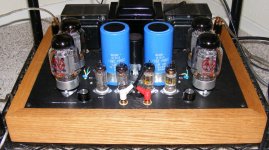
This amp is running my fave drive toobz 6kv8's. One can still get NOS sleeves of these for under $10 for the whole sleeve. Just remember to put those 5K grid stoppers on these video tubes.
This amp is running my fave drive toobz 6kv8's. One can still get NOS sleeves of these for under $10 for the whole sleeve. Just remember to put those 5K grid stoppers on these video tubes.
Attachments
I am building a P2P version with 6HJ5 tubes. I am aiming at a regulated B+ of about 400 volt with jan didden's T-regulator: http://www.linearaudio.nl/t-reg-1.htm.
I understand that the tubes should get 40 mA each.
I have a 60 volt winding on my power transformer. Anybody with a design for a regulated bias supply ?
I plan to use some old Fisher 6K6 outputtransformers (from x-100). Does anybody know what the upper current limit of these babies is ?
Jaap, for a regulated bias supply look at the amplifier of Norman Koren: The Emperor's New Amplifier 😉
Does anybody perhaps know how much mA the screensupply and the biassupply need (for one channel).
Figures help because I have to simulate/make different supply's than the original ones of P. Millett
Figures help because I have to simulate/make different supply's than the original ones of P. Millett
The negative voltage supply feeds the bias divider and the CCS under the input tubes. The input tubes draw 17 mA according to the schematic. The bias divider current will vary with the pot setting. I measure about 45 mA total current on my board (both channels) and my pot is near the negative extreme. The current will go up as the tube current is turned up. Figure 25 mA per channel.
The screen supply feeds the input tube screens and the output tube screens. The input tubes are fairly constant at 2 or 3 mA per channel but the output tube screen current is highly dependent of the tube being used, the plate voltage and how hard it is driven. If the plate voltage is low (in the 300 to 350 volt range the screen current can be 5 to 10 mA per tube at idle going to 25 or so when cranked. If the plate voltage is high (650 volts) the screen current is 1 or 2 mA per tube at idle going to 10 mA or so at 200 watts output. I have seen the meter go over 100 mA on my board (both channels cranked to the max with small tubea at 350 volts).
The plate current? Well lets just say I have seen over 1 amp at 650 volts! (35LR6 at 250 WPC).
The negative voltage supply feeds the bias divider and the CCS under the input tubes. The input tubes draw 17 mA according to the schematic. The bias divider current will vary with the pot setting. I measure about 45 mA total current on my board (both channels) and my pot is near the negative extreme. The current will go up as the tube current is turned up. Figure 25 mA per channel.
The screen supply feeds the input tube screens and the output tube screens. The input tubes are fairly constant at 2 or 3 mA per channel but the output tube screen current is highly dependent of the tube being used, the plate voltage and how hard it is driven. If the plate voltage is low (in the 300 to 350 volt range the screen current can be 5 to 10 mA per tube at idle going to 25 or so when cranked. If the plate voltage is high (650 volts) the screen current is 1 or 2 mA per tube at idle going to 10 mA or so at 200 watts output. I have seen the meter go over 100 mA on my board (both channels cranked to the max with small tubea at 350 volts).
The plate current? Well lets just say I have seen over 1 amp at 650 volts! (35LR6 at 250 WPC).
Thanks a lot ! I am planning 6HJ5 at 40 ma/400 volt B+; I am going to use gasregulators in the mosfet screensupply (because I had two holes left in the chassis)
Thanks a lot ! I am planning 6HJ5 at 40 ma/400 volt B+; I am going to use gasregulators in the mosfet screensupply (because I had two holes left in the chassis)
Love those gas regulator tubes😀, just so long as they're fed with a CCS, otherwise they tend to be noisy. But with a CCS, they are quiet even when feeding 1st stage phono. Sounds like you have a good plan. Best of luck.
Stuart
Hello,
I completed yesterday my build of the amplifier. It sounds well and shows distortion below 0.1% with NFB, however the power transformer get hot - perhaps to 60-70 C - and this doesn't seem to be the heat from the two MOSFETs. Is this normal? If not, what are the possible causes and where to look at?
The transformer is the recommended XPWR139 from Edcor, all voltages seem to be ok, cathode currents of the output tubes are adjusted to 40mA each.
Alex
Hello,
I completed yesterday my build of the amplifier. It sounds well and shows distortion below 0.1% with NFB, however the power transformer get hot - perhaps to 60-70 C - and this doesn't seem to be the heat from the two MOSFETs. Is this normal? If not, what are the possible causes and where to look at?
The transformer is the recommended XPWR139 from Edcor, all voltages seem to be ok, cathode currents of the output tubes are adjusted to 40mA each.
Alex
Hi Alex!
My DCPP uses the same power Edcor xfmr. After several hours of continuous operation, you can put your hand on it without fear. Regardless, the Edcor xfmrs are rated safe for more heat than your skin can stand. If everything measures well in your amp, don't worry. It's a great design and you will like it a lot. Remember to check the bias (40ma) after 25 hrs or so. After that the amp will settle down and be very stable.
I completed yesterday my build of the amplifier. It sounds well and shows distortion below 0.1% with NFB, however the power transformer get hot - perhaps to 60-70 C - and this doesn't seem to be the heat from the two MOSFETs. Is this normal? If not, what are the possible causes and where to look at?
FWIW, I'd guess mine is about the same temperature - I can put my hand on it but can just barely hold it there. I'm sure line voltage, frequency, and the output tube bias point all have an impact.
Pete
Hi there Pete! Glad you stopped by...
My DCPP is a very enjoyable amp. I have not found any need to modify a thing. It plays some days for hours on end, and has been totally reliable. A great piece of work!
My DCPP is a very enjoyable amp. I have not found any need to modify a thing. It plays some days for hours on end, and has been totally reliable. A great piece of work!
Pete and neonthecat, thank you for the quick replies. Sounds like I don't need to worry about the temperature of the transformer.
Also, Pete, thank you for documenting the project so well - it is almost as easy to build as a kit. The amp sounds very nice (even though my wife still prefers my Elekit TU-879S, a 8.5W SE amp with 6L6GCs).
Also, Pete, thank you for documenting the project so well - it is almost as easy to build as a kit. The amp sounds very nice (even though my wife still prefers my Elekit TU-879S, a 8.5W SE amp with 6L6GCs).
My ST70 (with VTA transformers) runs about that hot as well. After many hours of use, I can keep my hand on the power transformer for 3-5 seconds before it gets too painful. It is fairly normal and nothing to worry about as long as the area around it has decent ventilation.
I took a look at the Emperor's Amplifier schematic. The bias control circuits depicted are not regulated, rather they are servos. A problem with these is that they will shift the bias point when large signal is running thru the amp, especially if the amp is running pentode output tubes. That is likely why the builder is running the outputs as triodes (one still needs to be very careful with that servo scheme.) Another problem is that on a P-P amp there MUST be a feedback loop to balance the 2 AC gain paths. Sometimes this 'feedback' is simply a manual adjustment that is set occasionally.
I took a look at the Emperor's Amplifier schematic. The bias control circuits depicted are not regulated, rather they are servos. A problem with these is that they will shift the bias point when large signal is running thru the amp, especially if the amp is running pentode output tubes. That is likely why the builder is running the outputs as triodes (one still needs to be very careful with that servo scheme.) Another problem is that on a P-P amp there MUST be a feedback loop to balance the 2 AC gain paths. Sometimes this 'feedback' is simply a manual adjustment that is set occasionally.
It was my plan to use that IRF9610 schematic for the bias control of Pete Millett's design. So this is not a smart idea (?).
I can of course do the original CRC solution.
By the way, is R32 a bleeder ?
Maybe I missed something, but I see that Antek now lists an AN-4TK360 model. Like the AN-4TK400, it has 70V taps that can be used for the bias supply. But with 40 fewer volts of B+, it should be more manageable to build a souped-up DCPP using the stock caps.
http://www.antekinc.com/pdf/AN-4TK360.pdf
http://www.antekinc.com/pdf/AN-4TK360.pdf
It was my plan to use that IRF9610 schematic for the bias control of Pete Millett's design. So this is not a smart idea (?).
I can of course do the original CRC solution.
By the way, is R32 a bleeder ?
What I would do would be to run the completed amp to overload to check the servo response. Of course I am 'biased' against using transistors in my tube amps. When I do run transistors I use them as the output stage; this eliminates the costly output transformer and output tubes while maintaining that sweet tube sound. (also the distortion and damping are so good that minimal or no negative FB is required.)
A bridged single-ended N-Channel source-follower output stage (otherwise known as a Circlotron) works very nicely indeed.
I have been neglecting this project for some time as I had been trying to determine how to assemble the chassis but have decided forget about that and just get it working and then focus on the aesthetics. So I have been taking cliff notes on some of Georges comments and other than the slight modifications to the circuit to allow the 6HJ5s to be used shown by Rknize, here is what I have come up with.
- Change 220k ohm schade feedback resistors(R29, 30, 31, 47) to 2-3 two watt resistors in series to handle the voltage spikes
-Change R48, 49 to 10k 3watt
-I had purchased a few of these mosfets a while back with the idea they would work with the red board. With a proper insulator and heatsink hopefully they will fit the bill to replace the specified mosfet for Q2. With a little careful work with my needlenose pliers I have the lead spacing worked out and I am able to place it on the board.
Link to item: 2SK3675-01
-create FWB for bias supply utilizing 44v secondary off of transformer
-Omit the 820pf capacitors C7, 9, 10, 15
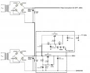
Now for the power supply I have yet again drawn up another amateur attempt. There was some talk about using current limiting resistors after the bridge rectifier before the first cap. I would assume with these larger caps this will be essential. I do have a handful of CL90s in a box some where from my move.
- Change 220k ohm schade feedback resistors(R29, 30, 31, 47) to 2-3 two watt resistors in series to handle the voltage spikes
-Change R48, 49 to 10k 3watt
-I had purchased a few of these mosfets a while back with the idea they would work with the red board. With a proper insulator and heatsink hopefully they will fit the bill to replace the specified mosfet for Q2. With a little careful work with my needlenose pliers I have the lead spacing worked out and I am able to place it on the board.
Link to item: 2SK3675-01
-create FWB for bias supply utilizing 44v secondary off of transformer
-Omit the 820pf capacitors C7, 9, 10, 15
Now for the power supply I have yet again drawn up another amateur attempt. There was some talk about using current limiting resistors after the bridge rectifier before the first cap. I would assume with these larger caps this will be essential. I do have a handful of CL90s in a box some where from my move.
Attachments
Last edited:
You also have to check R37 under the 10M45. Different batches have different specs. I tested mine first with two 9 volt batteries and I will use 120R resistors to get about 17 mA.
Is anybody using 0A2 regulator tubes in the screen supply instead of zeners ?
What resistor did you use in R33 ? I will try 680R first.
Is anybody using 0A2 regulator tubes in the screen supply instead of zeners ?
What resistor did you use in R33 ? I will try 680R first.
Eh my board still is bare with 2 10 pounders sitting beside it. Im still waiting on a final design so i can get 50-100 watts out of this.
Mine is pretty much populated minus a few items and I also forgot to order a couple of parts so I am planning to place an order with digikey one of these days.Eh my board still is bare with 2 10 pounders sitting beside it. Im still waiting on a final design so i can get 50-100 watts out of this.
- Home
- Amplifiers
- Tubes / Valves
- Posted new P-P power amp design