I would avoid connecting the power supplies in series after the solid state components. It just seems like an easy way to fry some silicon. It also puts much higher voltage and current drains on the regulators.
Connect a bridge and cap to each HV secondary. Wire these two simple supplies in series. The negative end of the bottom supply is connected to the PC board ground. The point where the two supplies are connected becomes the (300 to 350 volt) source for the PC board. The screen regulator and B+ filter on the PC board can be used, or external regulators could be used. These supplies provide screen voltage for all tubes and B+ voltage for the driver tubes. The current demands are low, lower than the original board since output tube plate current doesn't flow through these regulators.
The positive terminal from the top supply feeds the plates ot the output tubes through the OPT's. This supply will see large peak currents, a very wide range of current demands (80 mA to say an Amp) and 600 to 700 volts. I am not sure that this is a good place for a solid state regulator or filter, and I am not sure one is needed.
There are two current loops here and they should be seperated wherever possible. They must both pass through the bottom transformer and it's bridge and cap. Any further intermingling just complicates things.
If I get time I will sketch this up and post it. I have most of this wired up using bits and pieces from old projects. The mosfet screen regulator and mosfet B+ filter have never been populated. That is the missing link at this moment.
Sherri (my wife) is home for 6 days, probably for the last time this year. I doubt that the switch will get flipped this week.
Nic, that's what I'm doing also. However my variation is in building the power supply outboard and tapping a wire off through the power supply at exactly the place you did. Everyone seems to think I'm nuts for reusing a power supply for different amps. My regulator is the one on board the circuit board. But the rest of the power supply is outboard and includes 4 transformers configurable at approx 50 volt intervals from about 90 volts to 600 volts.
I'll post pictures when I'm closer to finishing it. Right now I'm completing the chassis work. It will be months before everything is done.
I just can't see buying new power transformers for every new project since the amps are built strictly for my use. Also it makes much more sense to me to have the magnetic interference from those xfmrs as far away as possible from the amplified signal.
I think me and Georges messages passed in the night. My 600 volt ( 1 each per channel and configurable) comes from isolated xfmrs. So, hopefully I can get away with tapping off power from a separate 300 volt xfmr for the regulator. I won't be using 2 xfmrs to add up to 600 volts. I'm sure he is right about your application needing having complications due to unequal load on the 2 halves of one VIRTUAL xfmr.
patrick turner's full wave voltage doubler are tops when it comes to simplicity and safety as far as power supplies are concerned, this link tells a lot.....if you need multiple voltages this topology is pretty much it.....😀
powersupplies
powersupplies
Very basic question here for a bone stock build. I'm using the socket from the BOM but could use some incite getting things wired up.
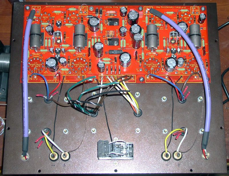
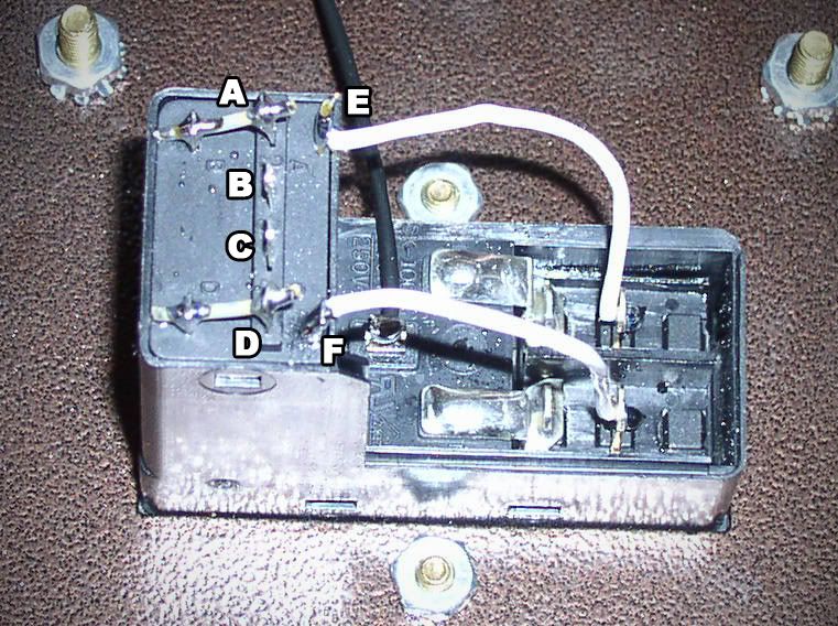
Could someone take a moment to tell me which wire (green, black, G/W, B/W) is soldered to each of the lettered points? TIA!
Could someone take a moment to tell me which wire (green, black, G/W, B/W) is soldered to each of the lettered points? TIA!
Very basic question here for a bone stock build. I'm using the socket from the BOM but could use some incite getting things wired up.
Could someone take a moment to tell me which wire (green, black, G/W, B/W) is soldered to each of the lettered points? TIA!
I have not used this exact inlet and hopefully somebody who has can tell us, but looking at the datasheet I think it actually matches the schematic:

I believe "A B C D" corresponds to "1 2 3 4" on the datasheet and the schematic. Are there numbers next to the terminals?
Pete
Are there numbers next to the terminals?
Yes. Your diagram appears to match the part, just "L" and "N" are reversed, which doesn't matter.
jeff
Last edited:
As Pete warned in his website notes for the DCPP, the switch/power module can be confusing. To be sure, I would suggest taking a few minutes with a DMM and check all the terminals for continuity and make/break. As a matter of fact, the module I used although having the same part# as on the BOM, had a different arrangement of the terminals. Also, a wiring diagram provided with the package, was for some other model, and was wrong for mine.
As Pete warned in his website notes for the DCPP, the switch/power module can be confusing. To be sure, I would suggest taking a few minutes with a DMM and check all the terminals for continuity and make/break. As a matter of fact, the module I used although having the same part# as on the BOM, had a different arrangement of the terminals. Also, a wiring diagram provided with the package, was for some other model, and was wrong for mine.
Ugh. Maybe next time I'll fork over the extra $5 for a Schurter

Thanks for the good info Pete, got it all wired up. I want to verify I have the fuse wired correctly and then I can fire it up.
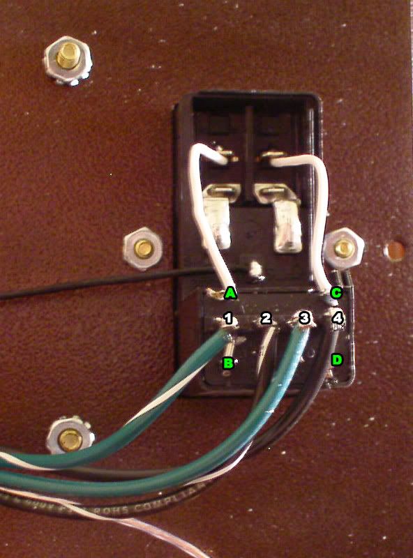
Note that I have terminal 1 wired to B and terminal 4 wired to D. If anyone who used the same socket can give me a quick verification, that would be great. Sorry that I'm being so cautious, but I don't want anything to burn up because of something easily remedied 😉
Note that I have terminal 1 wired to B and terminal 4 wired to D. If anyone who used the same socket can give me a quick verification, that would be great. Sorry that I'm being so cautious, but I don't want anything to burn up because of something easily remedied 😉
It looks like everything is in its place.
Here is mine for reference.
Here is mine for reference.
An externally hosted image should be here but it was not working when we last tested it.
Last edited:
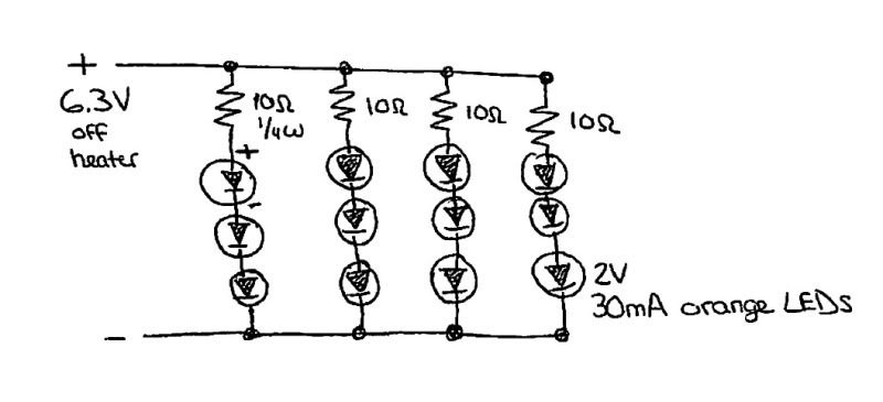
I've got a local shop building me a nice little wood base for this. The last thing on the agenda is to build an LED array to light up the logo.
I'm planning on building something like this:
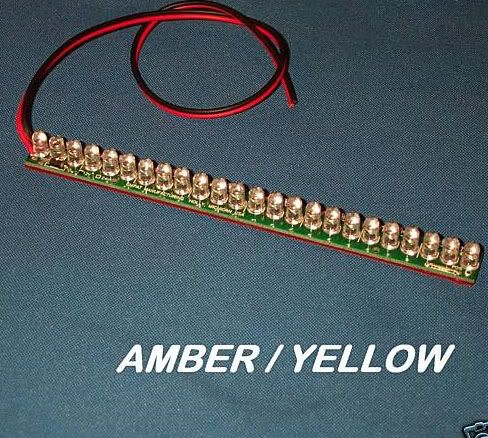
So I believe I should be able to run something like this off the 6.3V heater:
I'm planning on building something like this:
So I believe I should be able to run something like this off the 6.3V heater:
ufta...I have been trying to layout a chassis for this amp and having over 40lbs with just the transformers alone is proving to create a nice little challenge. I am thinking a two layer amp with the power supply on the bottom and the board and output transformers on the top. We have a pretty good blizzard going on here in Minnesota today so I may actually get some work put into this amp today!
We have a pretty good blizzard going on here in Minnesota today so I may actually get some work put into this amp today!
All week long we have seen record breaking temps (lows in the high 30's, highs in the 50's and 60's). The TV guys are whining about the loss of tourist revenue. They show live news reports from South Beach interviewing people claiming they should have stayed home. I was looking forward to dragging my speaker cabinets out into the driveway and finishing them but no....I wake up today and it is 80 degrees outside. So I am inside the flipping house with the AC on! At least I have the red board on the bench. No smoke yet.
Don't hate me yet. Next weekend I will be headed to snowy West Virginia (near Pittsburgh).
I have been trying to layout a chassis for this amp.....I am thinking a two layer amp with the power supply on the bottom and the board and output transformers on the top
I started on a two layer amp. It has not seen any activity is about a year though. I decided to put all of the transformers on the bottom deck out of view. They are all ugly toroids so they are best not seen. All of the tubes will go on the upper deck. It looks kinda funny to see no transformers on the deck though.
I am a bit jealous of your weather. I tried to leave the house once today and I got stuck in the street. I didn't realize the snow is 18 inches deep and they stopped plowing. We have had some white out conditions and a lot of wind.All week long we have seen record breaking temps (lows in the high 30's, highs in the 50's and 60's). The TV guys are whining about the loss of tourist revenue. They show live news reports from South Beach interviewing people claiming they should have stayed home. I was looking forward to dragging my speaker cabinets out into the driveway and finishing them but no....I wake up today and it is 80 degrees outside. So I am inside the flipping house with the AC on! At least I have the red board on the bench. No smoke yet.
I have a feeling the lower level is going to hold the two power transformers and the rest of the power supply components that are not mounted on the board and the top level will have the output transformers and main board. I purchased a couple of aluminum BUD 12x17x3 chassis a while ago for a heck of a deal from ApexJr which I think will work out really well for this project.I started on a two layer amp. It has not seen any activity is about a year though. I decided to put all of the transformers on the bottom deck out of view. They are all ugly toroids so they are best not seen. All of the tubes will go on the upper deck. It looks kinda funny to see no transformers on the deck though.
I have been working on this in my spare time. Since I don't have any spare time right now it isn't quite ready for prime time. All of my experiments on the red board so far have been with bench power supplies. That affords flexibility but makes it rather hard to take the amp anywhere. This discussion has led to the decision to build an amp using two "10 pound" power transformers. I am still missing a suitable pair of OPT's to complete the amp, but I have some suitable for testing.
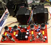
I mounted two 10 pounders on a piece of plywood. The OPT's and red board are not screwed down yet. I have swapped OPT's several times, and I need to work on the red board. I also used a recycled rectifier board from an old project. It has 8 caps and 16 diodes since it was intended for 1500 volts. It is being used to rectify and filter a 10 pound transformer for about 315 volts unloaded. A single cap and 4 diodes would do just fine, but I had this already made. Some experiments have been completed and sound has flowed forth. Full power testing has not happened yet. Progress so far:
I stripped most of my modifications from my red board. I restored it to the configuration that Pete intended. I populated the power supply section with the components shown in Petes BOM with one exception. I added 4 more power supply diodes to convert the FWCT rectifiers to FW bridges for operation with the 10 pound power transformer which does not have CT's on the bias or HV windings. The red board was last used with E130L output tubes which are octal. I simply sky wired the octal sockets right on top of the compactron sockets.
I will remove them when it is time to play with the big stuff, but I have seen these mild mannered tubes crank out 100 WPC and they sound really good. I fired the red board up on a single 10 pounder and got it to work. I could get anywhere from 20 WPC to 70 WPC out of it with a single power transformer depending on the load impedance. I used 6600 ohms, 3300 ohms, 2500 ohms, and 1250 ohms. The amp made 70 WPC with the 1250 ohm load but it isn't right. I wired the OPT CT directly to the rectifier output, bypassing the ripple filter since the mosfet started smoking. Previous experiments with these tubes show best sound and power comes with 600 volts and a 3300 ohm load.
I really wanted to have this thing running this year, but it is not to be. This weekend I must start on a 2500+ mile trip to see my mom, my wife, and her mom. The fireworks might be on new years eve.
Attachments
Good to hear minimal smoke was let out. Any idea why the mosfet started to smoke, dissipating too much heat?
Out of curiosity what output transformers do you have in the photo there?
Enjoy your time with your family. I am lucky that the majority of my family lives near with in a few hundred miles but it seems you never see each other enough.
Out of curiosity what output transformers do you have in the photo there?
Enjoy your time with your family. I am lucky that the majority of my family lives near with in a few hundred miles but it seems you never see each other enough.
dissipating too much heat?
Yes. I think that the total current for 4 E130L's running almost 70WPC must have been in the 1 amp range (didn't measure it). The voltage drop across the fet was 25 to 30 volts. I used a mosfet that is isolated (plastic coated) so I didn't need to mess with insulators. I think that they are only rated for 30 watts with a good heat sink. The heat sink that I have is not big enough so it was too hot to touch and the mosfet was so hot that it started to smoke. I powered off before meltdown and nothing was blown. The amp was misbehaving when pushed hard and I believe that it was related to the mosfet follower type ripple filter either oscillating or breaking down under pressure. There were no issues with the lighter loads which drew less current. The amp worked much better when the filter was bypassed on the OPT leads for the 1250 ohm test. A faint hum was evident.
This was all an attempt to run the entire amp from one 10 pounder, which was not intended to power 140 watts worth of amp. Neither was the mosfet filter. The next incarnation will use both power transformers and the mosfet ripple filter will only be powering the 6CB6's so there will be no heat issues.
The OPT's in the picture are from Handwound Transformers. This firm was started by a guy in Pennsylvania on Ebay. He auctioned his transformers with a low starting bid. I placed minimum bids on all of his auctions. I got a set of 845 SE transformers which are in my 845SE amp and work good. These were the second set I won which are "6600 ohm 60 watts". They will work OK at 6600 ohms in some circuits and seem to have no problem eating 100 watts. They distort badly above 10KHz in some circuits and are useless when wired as 3300 ohm OPT's. He blacklisted me from his auctions so I got no more cheap transformers. It seems that his later transformers were junk, and then he resorted to taking peoples money and sending nothing. He is no longer in business and from some of the comments I read may have been lynched!
I am building a P2P version with 6HJ5 tubes. I am aiming at a regulated B+ of about 400 volt with jan didden's T-regulator: http://www.linearaudio.nl/t-reg-1.htm.
I understand that the tubes should get 40 mA each.
I have a 60 volt winding on my power transformer. Anybody with a design for a regulated bias supply ?
I plan to use some old Fisher 6K6 outputtransformers (from x-100). Does anybody know what the upper current limit of these babies is ?
I understand that the tubes should get 40 mA each.
I have a 60 volt winding on my power transformer. Anybody with a design for a regulated bias supply ?
I plan to use some old Fisher 6K6 outputtransformers (from x-100). Does anybody know what the upper current limit of these babies is ?
- Home
- Amplifiers
- Tubes / Valves
- Posted new P-P power amp design