Yes please! 🙂
+1 this as well.
tubelab: while reading all your posts i was also thinking that the 6HJ5s would be the best for this amp (based off of your results). That would be amazing if you could thoroughly document a build with them that get 100+ WPC stable (which im sure it can).
I wonder when it leaves class A? The 20 watter left class A at 10 watts, or half max. There is no way a 100 watter leaves class A at 50 watts...
Aw man i hope i bought the right 10 pounders. I didnt know he was selling 2 styles with the same wattage and size. one is 330vdc and the other is 230vdc. I hope i was suppose to buy the 330 ones cuz thats what i got. I never heard tube lab mention use to in series to get 500vdc but i did hear him mention 600+ a few times.
The #7019 is the correct one. http://www.diyaudio.com/forums/tubes-valves/169867-10-pounds-power-15-a.html#post2236968
I have been working to finish this amp and I had a question about my transformer wiring. Since I am opting to use other iron my wiring is a bit different. The two transformers I am currently planning to use are the Antek an-4t360(HV and Heaters) and an-0225(bias supply)
1. First major difference is the transformer I currently have lacks a center tap on the 6.3v winding. Will this cause any issue if I just float it or should I look to find a transformer with a center tapped heater winding?
2. I have a smaller bias tap transformer that will be used with this. I was planning to wire the two windings in series and hook one end up to one of the diodes on the bias tap and run a half wave rectifier. The other end connected to ground. Sound correct?
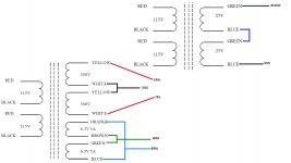
3. Have I got the wiring of the high voltage windings correct? I have a feeling in my diagram I should have tied the white wires together and put those to ground and have the yellow wires go to "ORN" and "YEL" on the board. Or tie the yellows together to ground and the whites to "ORN" and "YEL"?
4.Now that I look at the diagram again It looks like I even drew up my heater wiring wrong. Should it have been Tie Orange and Green together and Blue and Brown together so that they are in parallel?
Please see the attached photo to see my proposed wiring....I just wanted to make sure I have all my "I"s dotted and "T"s crossed before I end up firing this up.
**I have edited this a couple of times so there were a few things that I think I found was wrong with my diagram after I posted it.
1. First major difference is the transformer I currently have lacks a center tap on the 6.3v winding. Will this cause any issue if I just float it or should I look to find a transformer with a center tapped heater winding?
2. I have a smaller bias tap transformer that will be used with this. I was planning to wire the two windings in series and hook one end up to one of the diodes on the bias tap and run a half wave rectifier. The other end connected to ground. Sound correct?
3. Have I got the wiring of the high voltage windings correct? I have a feeling in my diagram I should have tied the white wires together and put those to ground and have the yellow wires go to "ORN" and "YEL" on the board. Or tie the yellows together to ground and the whites to "ORN" and "YEL"?
4.Now that I look at the diagram again It looks like I even drew up my heater wiring wrong. Should it have been Tie Orange and Green together and Blue and Brown together so that they are in parallel?
Please see the attached photo to see my proposed wiring....I just wanted to make sure I have all my "I"s dotted and "T"s crossed before I end up firing this up.
**I have edited this a couple of times so there were a few things that I think I found was wrong with my diagram after I posted it.
Attachments
Last edited:
B+ is wired correctly in the diagram. You took 2 360vac units and made one 720ct unit which is correct. Dont second guess yourself 🙂
ya fix your heater wiring the way you described (parallel). Jumper wh/br(ct) to brn. That will raise the heaters to the right level (your hooking 1 leg of the heaters to a voltage divider to keep the B+ from arching to the heater).
Your bias is wired correctly at the transformer(series), but you will have to make and off board full bridge rectifier (standard 4 diode like most electronics) and then jumper it in at R7 and ground.
Also make sure you check your bias voltages before you hook them to the board. Remember you want negative bias. you hook it up backwards and you will have +60v bias and some exploding bias caps. I guess you could say positive to ground and negative to the R7.
If you want to make it idiot proof, jumper the full bridge in at wh/or or wh/yl (or both if your want) and ground. Then when you fire it up, worse case scenario is zero bias (diodes will do their job of blocking the wrong polarity) instead of blowing up your bias supply caps.
Last edited:
Here is an updated diagram....which I think is now correct?
The high voltage supply now should be 360-0-360
Here is where I got the bias wiring from. I don't think I will need a fwb rectifier circuit
The high voltage supply now should be 360-0-360
Here is where I got the bias wiring from. I don't think I will need a fwb rectifier circuit
That doesn't work, since the B+ CT is grounded. But no problem using a single 50V bias tap as opposed to the two on the Edcor. Just connect the single 50V tap to one of the two diodes, and leave the other unconnected. It makes a half wave rectifier, but it works fine - I was running a Hammond 300-series transformer that way before I got the custom Edcor.
Pete
Attachments
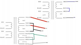
Nic, I think the B+ windings are now incorrect, but they are correct in the first diagram. One way to check is connect the inner white and yellow wires together (the centertap), and put a multimeter on the outside white and yellow wires, and you should measure 720V AC. But first check your multimeter can safely measure 720V AC. If you have the windings wired incorrectly, you will measure around 0V AC. On the only Antek tranny I have, wired like this with a centertap, I had to connect a white wire from one winding and a yellow wire from the other winding to ground (centertap).
Alright...I thought I was originally correct but I wasn't 100% sure. It is easy to confuse yourself by over analyzing.Nic, I think the B+ windings are now incorrect, but they are correct in the first diagram. One way to check is connect the inner white and yellow wires together (the centertap), and put a multimeter on the outside white and yellow wires, and you should measure 720V AC. But first check your multimeter can safely measure 720V AC. If you have the windings wired incorrectly, you will measure around 0V AC. On the only Antek tranny I have, wired like this with a centertap, I had to connect a white wire from one winding and a yellow wire from the other winding to ground (centertap).
I am going to hopefully mount everything temporarily to a piece of plywood for testing...hopefully by the end of the week we will be playing some tunes through it.
Is a half wave gonna work without changing cap values? Yes the voltage will be correct, but that cap has got to have enough juice to keep the voltage up through the blank cycle. If the cap was made to reduce the ripple between waves, then in theory the output voltage would be reduced by half.
Look i made a real simple diagram were you just have to air wire 2 diodes across the power input spot. So its just popping in 2 diodes from WH/OR and WH/YL to WHT
Look i made a real simple diagram were you just have to air wire 2 diodes across the power input spot. So its just popping in 2 diodes from WH/OR and WH/YL to WHT
An externally hosted image should be here but it was not working when we last tested it.
Last edited:
Hi all. I'm planning on building this amp but will be doing some modifications for higher power ( like so many others). Is it possible to tap off power for the regulated screen power right after the b+ filter instead of before it? I guess what I'm asking is if there will be any weird interaction between the two power mosfets. Thanks in advance.
and why would you do this? the screen is allready tapped off of the B+ rectifier/cap. the b+ mosfet is just for a ripple filter, while the screen mosfet se a 150v regulator.
There would be no point to tap the 150v regular after the ripple filter since it already is a ripple filter.
It would work, but i think it would sound worse. Any noise is filtered out by the mosfets. If you introduce a regulator after a regulator then the noise of the 2nd regulator cant be filtered out by the first.
and why would you do this? the screen is allready tapped off of the B+ rectifier/cap. the b+ mosfet is just for a ripple filter, while the screen mosfet se a 150v regulator.
There would be no point to tap the 150v regular after the ripple filter since it already is a ripple filter.
It would work, but i think it would sound worse. Any noise is filtered out by the mosfets. If you introduce a regulator after a regulator then the noise of the 2nd regulator cant be filtered out by the first.
I'm offloading the power supply duties to a separate chassis. It is more convenient for me to have the regulator(s) on the actual amp to eliminate the extra wires for it in the umbilical. Regulators are voltage specifiic to
Particular amps. I plan on eliminating power supplies for future amp builds of mine and reuse the one I'm building for them. That means tapping off the filtered supplies coming into the amps.
I can already see that this can easily go off topic so if at all possible can we stick to my specific original question. Thanks much.
Ok it will work.
BUT.
Any noise generated by the bias regulator will be sent unfiltered to the b+. Thats why its best to have each rail have its own regulator/filter. The noise might be so nill that it doesnt matter and we are just splitting hairs.
People do this all the time with DACs. They have a 5v regulator for the analog section, then they tap a 3.3 regulator from the 5v rail. Most of the time it works out great.
Back to the original question, the 2 mosfets dont care. You can pop one right after the other. The first one just filters out some ripple and filters out some noise. It so over built it could care less about the load. The other mosfet is a 150v regulator that could care less about were its getting its power from. There could be a 300vdc rail with a 100v ripple and it would be fine.
Ok it will work.
BUT.
Any noise generated by the bias regulator will be sent unfiltered to the b+. Thats why its best to have each rail have its own regulator/filter. The noise might be so nill that it doesnt matter and we are just splitting hairs.
Good point. The power supply will use 4 xfmrs, 2 big ones and 2 medium ones.
I'll just remember to assign regulated voltages to their own isolated xfmr. Flexibility is good.
For fun I am having a go at building the amp.
I'm a bit puzzled by R68 and R70 (3.3K 0.5w). I can't see them on the schematic and I see they are connected at one end only to R66 and R65, but apparently nothing at the other end.
Any help would be appreciated.
ray
I'm a bit puzzled by R68 and R70 (3.3K 0.5w). I can't see them on the schematic and I see they are connected at one end only to R66 and R65, but apparently nothing at the other end.
Any help would be appreciated.
ray
My apologies. I found them connected to ground.
One of the joys of getting older is that you can't find anything.
ray
One of the joys of getting older is that you can't find anything.
ray
I'm not sure why it doesn't show up on the schematic you are looking at. On the one I'm seeing r68 and r70 connect to signal grd on one end and the other end connects between r65and r71 and between r66 and r72 respectively. R68 and r70 are the reference to ground for one grid of input differential tubes and for gfb feedback circuit (if implemented) from the secondary of the opt. Hope that helps.
pete
An octal sweep design would be very cool but that wont stop me from trying out the current version.
George; sign me up as one interested in seeing what your are able to decide as the final result. I've been having fun reading/learning taxing the grey cells to understand everything you are doing but mostly having a good read on the progress. Looking forward to seeing what you design.
erick
- Home
- Amplifiers
- Tubes / Valves
- Posted new P-P power amp design