I used to have some 2 channel "Celco" deflection amplifiers. Rack mount, SS. They had the sense resistor in the ground return lead also.
Yeah, the inductor should do a linear current ramp with just a constant voltage applied, except for internal wire resistance modifying that to a saturating LR response.
We are lucky that these "switch mode" TV tubes are fairly linear still. Some even have quite nice triode mode curves.
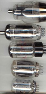
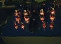
Tube comparison pic:
1625 (807) top
35LR6
6L6GC
21HB5A
6GE5 (6JN6) bottom
Yeah, the inductor should do a linear current ramp with just a constant voltage applied, except for internal wire resistance modifying that to a saturating LR response.
We are lucky that these "switch mode" TV tubes are fairly linear still. Some even have quite nice triode mode curves.
Tube comparison pic:
1625 (807) top
35LR6
6L6GC
21HB5A
6GE5 (6JN6) bottom
Attachments
Last edited:
For air core yoke coils, there is no saturating core.
The coil wire resistance limits the current, if the ramp voltage has stopped to a steady state.
For inductors, voltage leads the current, which is why the voltage rises faster than the current at the beginning of the sweep ramp. How easy that is to observe depends on the amount of inductance and the rising rate of the ramp current (Amp/sec). Any large distributed capacitance will affect the overall effect too.
Last edited:
The yokes in the TV sets I worked on (pre 1972) had ferrite cores. We were a Philco factory service shop, so at least half of out work was Philco. We would get a bad yoke every so often. They either had shorted turns, or cracked ferrite. Either way you got a trapezoidal picture. We had a few that had burst into flames, with one so violent it cracked the CRT. Must not have been too uncommon because Philco paid for the repair even though the TV was just beyond the warantee period.
Sylvania made some ugly metal cabinet TV's that never broke down. The usual calls on them were from people getting shocked from the metal box.
Sylvania made some ugly metal cabinet TV's that never broke down. The usual calls on them were from people getting shocked from the metal box.
i made a pp amp out of pairs of 12EN6 octals, that amp bested a Leben el84 pp amp costing 8 times more than what i spent on my amp...
Too bad those ferrite deflection cores won't stack up some way to make a giant OT core.
12EN6 is on the $1 list.
But you can build the whole amplifier with 6MF8 or 6KY8 (also on the list).
12EN6 is on the $1 list.
But you can build the whole amplifier with 6MF8 or 6KY8 (also on the list).
I found these posts useful.
551 - FQP8N60C fets
FQP8N60C EOL at Fairchild
how does the 6ew6 compare with a 6AM6, or a 6BX6?
I haven't used 6EW6s for audio, just RF. There, they do seem to perform quite well: lots of gain, can use lowish V2K which helps when using them for grid detection. Decent audio recovery, so should be usable for audio in cases where you need lots of voltage gain.
I had a bag full of used 6EW6's, maybe 50 of them. I stuffed them one by one into the red board way back when. As others said the used ones seem to suck. Some had plenty of gain, but finding a pair that yielded low distortion in the red board was difficult.
Many of the early vintage high GM tubes share this trait. Finding good 6EJ7's that play well together is not easy either, and compounded by the myriad of different constructions.
I only had 3 NOS 6EW6's, and I did get two of them to play nice together, but abandoned the effort when I found that just about ant two random 6GU5's worked, and provided enough gain to clip my 125 WPC version when driven by my CD player.
I had a bag full of used 6EW6's, maybe 50 of them. I stuffed them one by one into the red board way back when. As others said the used ones seem to suck. Some had plenty of gain, but finding a pair that yielded low distortion in the red board was difficult.
No surprises there. The 6EW6 was intended for IF duty, and even though it's a small signal type, manufacturers typically ran them hard. Even the data sheet recommends VPK= 125V and IP= 11.0mA for a PD= 1.375W -- over 1/3rd of the PD rating. They probably pushed that recommend a lot farther. In All American-5 AM xcvrs, the IF tube gets as hot as the power diode and audio final. You almost never see that in audio stages with passive plate loading. Heavy current means higher gain. They really didn't care back when just about every convenience store, pharmacy, grocery store had those "U Test 'Em" machines and stocks of the most common types. Didn't matter if the 6EW6s wore out quickly.
(They also did other horrible things, like this old record player amp that used PP 6V6s as finals, and a 5Y3 dual diode operating straight into a 100uF reservoir capacitor. That busts the Isurge spec by quite a large margin, but what did they care? The average consumer isn't going to know it's a hideous design, nor know there's something wrong when they have to be replacing 5Y3s all the time.)
Many of the early vintage high GM tubes share this trait. Finding good 6EJ7's that play well together is not easy either, and compounded by the myriad of different constructions.
I only had 3 NOS 6EW6's, and I did get two of them to play nice together, but abandoned the effort when I found that just about ant two random 6GU5's worked, and provided enough gain to clip my 125 WPC version when driven by my CD player.
Hard to find good audio loadlines for pents. That's why Norman Crowhurst avoided the subject, and why lazy designers will use two and three triode stages instead of one pentode stage. so far, haven't needed that much audio gain, though I have used them for RF designs, including a simple AM BCB xcvr to avoid the necessity for regeneration used with triodes to get the RF gain. Fresh 6EW6s not borked work well for this.
Hi all,
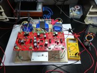
I have built the 1st tube power amp in my young career and I am ready to test it. I hooked all the things to a Variac, digital multimeters, etc, and read the adjustement procedure outlined by Pete.
Inputs are shorted, NFB disconnected, as I'm not sure about the plate polarity being correct, so I want to avoid putting positive feedback in while I power it for the first time.
What I'm not sure about is whether I need to put loads on the output. I have fake HP loads as power resistors in 4, 8, 16 ohms values. My guess is, better test with load but Pete isn't really precise about this. Hints welcome !
Charles
Attachments
Last edited:
Thanks Jazbo8. The amp is going great, now playing music. No trouble to match the biases, loafing along with everything I throw at it, from soft Mark Knopfer till In Flames metal. Impressive sound. Now on to build a case. Pete: respect, that is great work you did !
Hi again,
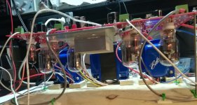
While I'm doing some CAD work to accommodate my connectors to the front plane, I took some measures after about 4-5 hours burn-in. The tubes seems to slowly stabilize around 40 mA, even if I'm checking and adjusting the current from time to time.
My line voltage is about 227-230V, 50Hz. Plate voltage is at 370V, which seems a bit over the range mentioned in the PSU schema (340 +/- 20). I'm still under the capacitor limits, so I guess this is ok.
I haven't got my front-plate yet, so I have screwed the FETs to an aluminum plate and a nice heatsink. The alu plate is only 20x10cm, 3mm thick. Its temperature rises to about 43°C (110°F). Probably a bit too high, I expect it to be lower when my amp has the tubes upwards. Right now it's upside-down on my bread-board, with the heat of tubes radiating in the wrong direction.
If you think my values are completely off-limits, please chime in !
Meanwhile I've got my favorite feed playing, and it sounds awesome !
Thx, Charles
Attachments
Dear all,
Even if the amp sounds fine, I re-made all measurements, and I think some values are a bit too high. I measured them without input signal.
Can I test Q2 or D9 with a DMM without de-soldering them and without risking to freeze them if not already done ?
Thx for your assistance !!!
Charles
Even if the amp sounds fine, I re-made all measurements, and I think some values are a bit too high. I measured them without input signal.
- my wall power is 228V AC, 50 Hz
- after RT1 : 396V
- B+ : 390V
- G2 (screen) : 140V
- C- (bias) : -68V
- plates : 384V
- RDP1/2 : 216V
- LDP1/2 : 219V
Can I test Q2 or D9 with a DMM without de-soldering them and without risking to freeze them if not already done ?
Thx for your assistance !!!
Charles
vertical output tubes are not more than 10 watt but very good sound like pcl82.... 7 watt .... nice mid.horizontal output tubes more power . .
hifi uk design..... el519...
An externally hosted image should be here but it was not working when we last tested it.
hifi uk design..... el519...
Last edited:
Hello everyone:
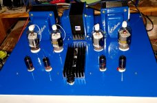
Another engineer's amplifier is now alive! Got the board 2 and a half years ago, stuffed it quickly and then patiently started to wait for Edcor transformers. Since I could not leave well enough alone, I upgraded the power transformer slightly (xpwr205, only difference being a slightly higher 300-0-300 winding from the stock xpwr139) and kind of overdid it with two cxpp50-6.6 . Once I go them, I kind got sidetracked by all kinds of other things so the entire project went dormant.
Yesterday I finally finished the wiring and passed the first smoke test. But no working amp 🙁
This morning I checked q1, and realized that my soldering job to the Drain pin of q1 had not succeeded. Fix that one and I had ...sound!
Everything adjusted right up and it now sound pretty nice. Happy camper!
This is tube amp #3 (Tu-8200 kit, SimplePP by Tubelab and now this). When is enough enough? I think I know the answer but... 🙂
Attachments
Hello Phy, congrats for your build ! seems your wife likes blue 🙂
After having read all the thread content, I would like to build the same amp (got two more PCB from Pete) but with more power with the so-called boosted-B+. My idea is to buy OPT and PSU transformers from Toroidy in Poland. Not that I'm unhappy with Edcor good products, but the shipping costs from USA to Switzerland plus the non-EU customs taxes are dissuasive.
I still have to talk to Toroidy wheter they can make the stuff I want, and check what power and setup I can get from my 6JN6 stack.
Regs,
Charles
Dear all,
Even if the amp sounds fine, I re-made all measurements, and I think some values are a bit too high. I measured them without input signal.
The small voltage diff over Q2 is suspect to me : did I freeze Q2 or D9 ?
- my wall power is 228V AC, 50 Hz
- after RT1 : 396V
- B+ : 390V
- G2 (screen) : 140V
- C- (bias) : -68V
- plates : 384V
- RDP1/2 : 216V
- LDP1/2 : 219V
Can I test Q2 or D9 with a DMM without de-soldering them and without risking to freeze them if not already done ?
Thx for your assistance !!!
Charles
I swapped Q2 and D9 and the B+ is still about 388V. I checked all the resistor values, etc. Now I'm not sure how the circuit around Q2 works...
Maybe I do not have a real issue, if the voltage is high only because my power tranny gives higher voltage than expected : it produces twice 313V instead of the expected 280 of its spec.
Hints welcome.
Maybe I do not have a real issue, if the voltage is high only because my power tranny gives higher voltage than expected : it produces twice 313V instead of the expected 280 of its spec.
I think someone would have said something by now if this was a problem.
jeff
- Home
- Amplifiers
- Tubes / Valves
- Posted new P-P power amp design