An octal sweep design would be very cool but that wont stop me from trying out the current version.
It is possible to wire octal sockets into the existing board. In fact my board currently has octal sockets in it.
George; sign me up as one interested in seeing what your are able to decide as the final result.
My original board still has some life left in it. The current plan is to use that board to find a working solution that fulfills the design criteria. The working solution will then be implemented on a fresh board and built into a complete amp.
Design criteria:
The most popular request calls for an output power in the 100 watt per channel range. The design should be implementable by most builders. No unobtainable components should be used. For most builders the big ticket items are the tubes and transformers. Some experimenting has already been done and this is what I know so far:
Anyone contemplating this build would be wise to reread the entire thread. I plan to go through it one more time. From my previous experiments I have found several different ways to get to 100 WPC. I have tried 6600 ohm OPT's because I have some, but it seems that you need well over 700 volts to get 100 WPC. With a 5K OPT 100 WPC can be realized with 600 volts or so and tubes that can saturate down to 50 volts or so. 3.3K will work at 550 volts or so. So we need an OPT that can handle 100 watts in the 3.3K to 5K ohm range. Guess what I don't have. I made arangements to purchase a pair of Edcor 3.3K OPT's from another forum member, so the experiments will start when they arrive.
The power transformer is another wild card. I am sure that it can be done with one or two big Antek toroids, and of course the 10 pounds for $15 transformers will be tested too.
The tubes should be the easy part. I have seen several combinations that will work. I plan to test quite a few, and I suspect that there will be several choices for a given build.
I kept some scribbles of notes of this thread, seems there was action (as far as higher power) at these post numbers:
138 139 144 145 149 153 168 170 196 218 222 228 232 248 255 267 270 273 293
Some heavyweight action was at these posts 168 196 218 222 270
There could be others, as my scribbles only go to post 293, and I could have missed some, but these numbers might save a bit of searching for anything from 50W to 240W per channel.
I found these posts useful.
1 – initial post - DCPP Amp
82 – 500 volt caps
138 – voltage tolerances
139 – using 450 volts
145 – alternate tubes – see #557
149 – 40 ma for bias current
153 – current draws
168 – mod to R48 & R49
170 – current draw at high voltages
196 - 6LF6 at 600V
205 – source of compactron sockets
218 – using 6KD6s
222 - 6GU5 as driver
228 – using 6LR6s
232 – power / distortion levels for 6HJ5
236 – 6HJ5 mods to wiring socket
248 – using 6JB5/6HE5/6JC5
255 – drive requirements for 6HJ5 grids
262 – curves for 35LR6
267 – screen drive
270 – using 6LF6s
293 - 6HJ5 will work fine with 150 volts on the screen
336 – max volts for 6JN6
345 – reminder to increase R21 value
346 – photo of mod to run 6HJ5
394 – 399 – 7 pin sockets
422 – higher power tips – new resistor values – important info here
423 – mixing 6 and 35 volt tubes on same board
437 - 35LR6's output distortion levels
462 - 6HJ5 in Schade mode on the curve tracer
465 – octal socket wiring
544 - 115:12.6VAC transformer hooked up backwards to the 6.3V winding giving 58VAC out
549 - 50watts from 6GV5 100watts from 6HJ5 200watts from 35LR6
551 - FQP8N60C fets
552 – series resistors for feedback
557 – notes on different tubes at higher power levels – some mods for some of the tubes
558 – 6GU5 as driver
565 – wiring for Antek toroid – see additional following posts
581 – voltage / output transformer impedence for various power levels
powerdrive with mosfet a la tubelab
I wonder if you have already tried powerdrive on this design.
I am going to find out. I believe that this amp would benefit from PowerDrive, so one of the experiments that I plan to do is to sky wire in some mosfets. It might be a week or two before I get back to it though. It doesn't look too hard to do, but I have to fix the toasted parts and modify the power supply first.
I wonder if you have already tried powerdrive on this design.
I wonder if you have already tried powerdrive on this design.
Yes, I briefly experimented with mosfet drivers in this board, but It only took me a few minutes to blow up the fets. I believe that oscillation was to blame and my implementation was far less than clean. I planned to try again, but when I found 100 to 250 watts per channel was easy to get, I never got back to it. Blocking distortion and overload recovery aren't much of an issue when your average listening level is 4 or 5 watts and you have 500.
I haven't had a blowup with mosfet drivers yet, but I think the key is to make sure the stoppers are adequate ( use at least 220 ohms, and 1k is probably better as a start - better too slow than too dead) and to to be sure to put bidirectional clamps on the gates, so that they can't get hammered on either polarity.
I haven't had a blowup with mosfet drivers yet
I quit collecting the dead ones a while ago. Most of the casualties came from screen drive experiments though. It took a fair pile of dead fets to find that current flows into a screen grid, but it can also flow OUT of it.
I used 1K gate stoppers and mosfets with internal zeners (2SK2700). Unfortunately the drains were wired to the supply with clip leads and I forgot my usual bypass cap at the fet. I also soldered the source to a flying connection, the grid stopper, and a 20K resistor to the negative supply. The gate lead was soldered to the stopper which was stuck into the hole where the original grid stopper was.
Everything biased up normally and as I started to apply drive the power started to flow, and then zap both fets blow up. In my previous experience this kind of destruction is oscillation, but I didn't actually see it happen. It could have just been one of those days.
I don't really trust internal protection zeners, probably from experience with the old VN10KM, where the internal zener acted like everything but a zener. As a result, I like the zeners out where I can see them. I understand about those days, too, though mine are usually accompanied by frustration rather than flame. I've settled on using the Fairchild FQP1N50 - but then, I just checked and they're obsoleting that part out from under me - I'll have to search again when I run out of the tube I have. It seems like a lot of the little TO-220 parts are getting the ax.
Thanks for the heads up though - I'll look harder at the corner operation of the source followers when I finally build my big P-P screen driven amp. You really can't push the screen driven SE amps hard enough to get into a lot of trouble. With P-P, it's a different story.
Thanks for the heads up though - I'll look harder at the corner operation of the source followers when I finally build my big P-P screen driven amp. You really can't push the screen driven SE amps hard enough to get into a lot of trouble. With P-P, it's a different story.
Last edited:
As a result, I like the zeners out where I can see them.
I haven't seen anything that pointed to non zener activity on the 2SK2700's but those went obsolete a few years ago and my stash is nearly gone. The 2SK3563 is still around and works up to 500 volts. I used external zeners with the IRF830's.
I've settled on using the Fairchild FQP1N50
I still have a few of those too.
You really can't push the screen driven SE amps hard enough to get into a lot of trouble. With P-P, it's a different story.
The problem is magnified with sweep tubes. It is not uncommon to run a sweep tube with a lot of voltage on the plate. The screen grid will have a fairly low voltage say 0 to 150 volts. If the grid is driven hard enough to make it glow, it will emit electrons, which will be quickly gobbled up by the large positive potential on the plate. A runaway will quickly ensue leading to mosfet pieces being scattered all over the room. In one case the mosfets, the screen supply and the output tube all blew up. Of course I was extracting over 100 watts out of a pair of 98 cent 6BQ6's.
One way to prevent that particular blowup mode from happening is to limit the voltage available at the drain of the follower FET. 100-120V will kick the living snot out of just about any screen driven sweep tube.
I was sniffing around at Digi-Key and Mouser last night, looking for decent candidates for source followers, namely small devices with low gate charge. They're getting pretty thin on the ground. I located an Ixys device that looks attractive. It also has a 600V VDS rating, which is a plus. One minus is that it's in a standard TO-220 package rather than with an insulated tab, but I can deal with that. They're cheap, so I placed an order for a bunch, as well as a couple of flavors of deplection mode fets, also from Ixys. Anyone with the gumption to work the parametric search engine for a couple of minutes will be able to locate the small mosfet at Digi-Key.
I was sniffing around at Digi-Key and Mouser last night, looking for decent candidates for source followers, namely small devices with low gate charge. They're getting pretty thin on the ground. I located an Ixys device that looks attractive. It also has a 600V VDS rating, which is a plus. One minus is that it's in a standard TO-220 package rather than with an insulated tab, but I can deal with that. They're cheap, so I placed an order for a bunch, as well as a couple of flavors of deplection mode fets, also from Ixys. Anyone with the gumption to work the parametric search engine for a couple of minutes will be able to locate the small mosfet at Digi-Key.

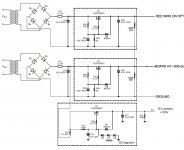
Not sure if this is sort of what you had in mind George for the screen and B+ supply?
Sort of. I have figured it all out in my head, but haven't tried it yet. This is my current "big idea".
Pete designed the board to run from a supply of about 340 volts. Each half of your supply should develop about 320 volts based on some experiments with the $15 transformers. It would seem that the unmodified board should be able to run from the bottom half of the supply. In fact I think that the on board power supply can be used by adding two diodes and maybe a big fat off board cap. I plan to test this in the near future.
The second transformer is wired to a second bridge and CLC filter just as you have drawn and ONLY feeds the red wires on the two OPT's (Edcor may use a different color). That is the only place where 600+ volts is needed. This arangement keeps the big voltages off the board and should prevent the exploding capacitor issues that I witnessed. In fact 450 volt caps should be OK for the PC board.
The only components that will need upgrading on the PC board are the Schade feedback resistors since they will see twice the total B+ voltage under signal peaks. I realized that the poor resistors on my board have been subjected to over 1300 volts on peaks and they are still alive, but others may not be so lucky. 1500 volt rated resistors aren't on the shelf at Walmart so 2 or 3 two watt resistors could be wired in series.
I may get some time to play this weekend, but Sherri is scheduled to come home on Tuesday for an unspecified period of time.
Pete, I am an electrical engineer, and I found your design (Engineer's amp) simply fascinating. I am not quite sure if people have already thought about an interesting power supply solution for tube amplifiers. I am talking about switch mode power supplies (SMPS) to generate 380V dc. Any modern SMPS with active power factor correction (PFC) circuit internally generates a 380V dc bus, and this bus is rated at the full capacity of the power supply. The problem would be galvanic isolation as this 380V bus is not magnetically isolated from the 120V mains. The older generation 250W power supplies could be as cheap as $20 in some surplus stores.
I like the sound of being able to use 450v caps. They are easy to find and Digikey seems to have stopped selling the 500v panasonics they used to stock. I just found some Nippon Chemicon KXG 450v caps for $1 a piece.The second transformer is wired to a second bridge and CLC filter just as you have drawn and ONLY feeds the red wires on the two OPT's (Edcor may use a different color). That is the only place where 600+ volts is needed. This arangement keeps the big voltages off the board and should prevent the exploding capacitor issues that I witnessed. In fact 450 volt caps should be OK for the PC board.
I have been attempting to determine the choke current ratings but I am unsure of my math. Any idea what the minimum current rating I could get away with for the power supply chokes I have shown? I have found some military surplus chokes that are reasonable, certainly not as cheap as the triad chokes.
I just found some Nippon Chemicon KXG 450v caps for $1 a piece.
I just bought a bunch of these:
Package of 50 Compact 47µF 450V Radial Electrolytic Caps-The Electronic Goldmine
And for RLD fans:
SALE! LITEON LTL912SEKSA "Piranha" 3.37 Lumen Red LED-The Electronic Goldmine
No you can't expect to stick 1000 LED's in the cathodes of these sweep tubes, but expect to see a glowing Simple P-P in the near future.
Any idea what the minimum current rating I could get away with for the power supply chokes I have shown?
Using the schematic as shown both chokes must pass the full current drawn by the output tubes. This could be 500 mA or more on peaks. The top choke must be insulated for 650 volts or more. The cheap Triads might catch fire in this application. With the 600 MEGA FARAD caps we might not need any chokes if we can figure out how to keep the diodes from exploding. I think inrush limiters on both sides of the transformer will be needed here.
Thanks!
You always post great deals! I picked up a bag as well.
Athos
I just bought a bunch of these:
Package of 50 Compact 47µF 450V Radial Electrolytic Caps-The Electronic Goldmine
And for RLD fans:
SALE! LITEON LTL912SEKSA "Piranha" 3.37 Lumen Red LED-The Electronic Goldmine
No you can't expect to stick 1000 LED's in the cathodes of these sweep tubes, but expect to see a glowing Simple P-P in the near future.
Using the schematic as shown both chokes must pass the full current drawn by the output tubes. This could be 500 mA or more on peaks. The top choke must be insulated for 650 volts or more. The cheap Triads might catch fire in this application. With the 600 MEGA FARAD caps we might not need any chokes if we can figure out how to keep the diodes from exploding. I think inrush limiters on both sides of the transformer will be needed here.
You always post great deals! I picked up a bag as well.
Athos
You always post great deals! I picked up a bag as well.
Don't thank me for this one. Forum member GEEK has his own forum. I learned about the caps from him. Found the diodes when looking around. There is also some Panasonic .33uf 250 volt caps for the ridiculous price of $3 for 100. I got plenty of all three items. I just ordered them this morning, but I have ordered from them before with good results.
Cheap caps
Alright I got to thinking some more and realized I had enough parts to build a second power supply just as it is seen on the schematic. So both supplies are wired in series. Anyone see anything wrong with the proposed schematic? I too purchased a bag of those nichicons. I think I am now set for life.
Attachments
- Home
- Amplifiers
- Tubes / Valves
- Posted new P-P power amp design